


28 Mechanical installation
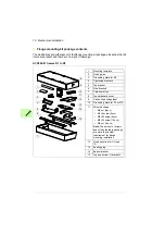
11. Attach chains to the drive lifting holes and lift the drive with a lifting device onto the
opening in the mounting plate.
12. Attach the bottom bracket with one screw.
13. Attach the top bracket with one screw.
14. Attach the rest of the mounting screws. Remove the chains.
11
12
13
14
1 × M6×25 screw
6 N·m
1 × M6×25 screw
6 N·m
R1: 8 × M6×25 screw
R2: 10 × M6×25 screw
R3: 12 × M6×25 screw
6 N·m
Summary of Contents for ACX580-01 R1
Page 1: ...ABB drives Supplement ACX580 01 R1 R3 Flange mounting kit installation ...
Page 4: ......
Page 12: ...12 Hardware description ...
Page 30: ...30 Dimension drawings ACX580 01 frame R1 Flange mounting kit 3AXD50000131310 ...
Page 31: ...Dimension drawings 31 Hood is needed for UL Type 12 drives 3AXD50000131242 ...
Page 32: ...32 Dimension drawings Attaching points and hole dimensions 3AXD50000038098 ...
Page 33: ...Dimension drawings 33 ACX580 01 frame R2 Flange mounting kit 3AXD50000131327 ...
Page 34: ...34 Dimension drawings Hood is needed for UL Type 12 drives 3AXD50000130863 ...
Page 35: ...Dimension drawings 35 Attaching points and hole dimensions 3AXD50000038111 ...
Page 36: ...36 Dimension drawings ACX580 01 frame R3 Flange mounting kit 3AXD50000131143 ...
Page 37: ...Dimension drawings 37 Hood is needed for UL Type 12 drives 3AXD50000130870 ...
Page 38: ...38 Dimension drawings Attaching points and hole dimensions 3AXD50000038117 ...
Page 40: ...Contact us www abb com drives www abb com drivespartners 3AXD50000119189 RevA EN 2017 10 10 ...


