


Guidelines for planning electrical installation 39
Minimizing electromagnetic interference
Obey these rules in order to minimize the electromagnetic interference caused by rapid
current changes in the energy storage cables:
•
Shield the energy storage cabling completely, either by using shielded cable or a
metallic enclosure. Unshielded single-core cable can only be used if it is routed inside
a cabinet that efficiently suppresses radiated emissions.
•
Install the cables away from other cable routes.
•
Avoid long parallel runs with other cables. The minimum parallel cabling separation
distance should be 0.3 meters.
•
Cross other cables at right angles.
Keep the cable as short as possible in order to minimize
the radiated emissions
and stress
on converter IGBT semiconductors. The longer the cable, the higher the radiated
emissions, inductive load and voltage peaks over the IGBTs of the DC/DC converter.
Maximum cable length
The maximum cable length of the energy storage cable(s) is 100 m (328 ft).
EMC compliance of the complete installation
Note:
ABB has not verified that the EMC requirements are fulfilled with external energy
storage and its cabling. The EMC compliance of the complete installation must be
considered by the customer.
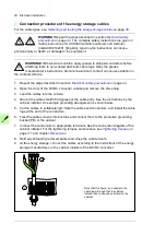
Protecting the system against thermal overload
For more information on the thermal protection function, see the appropriate firmware
manual.
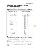
Protecting the energy storage cable against short-circuits
The DC/DC converter unit is equipped with DC fuses as standard. The fuses protect the
DC/DC converter and cables in a cable short-circuit situation.
The customer must equip the energy storage with fuses for protecting the energy storage
cable in a cable short-circuit situation.
Summary of Contents for ACS880-1607
Page 1: ...ABB industrial drives Hardware manual ACS880 1607 DC DC converter units ...
Page 4: ......
Page 12: ...12 Introduction to the manual ...
Page 34: ...34 Mechanical installation ...
Page 40: ...40 Guidelines for planning electrical installation ...
Page 52: ...52 Electrical installation ...
Page 68: ...68 Start up ...
Page 80: ...80 Maintenance 7 3 4 5 6 ...
Page 82: ...82 Maintenance 3 4 5 6 7 8 9 9 ...
Page 85: ...Maintenance 85 12 Install and tighten the two screws 10 11 12 ...
Page 92: ...92 Maintenance 3 6 4 5 4 7a 7b 7b ...
Page 93: ...Maintenance 93 9 8 8 10 11 ...
Page 96: ...96 Maintenance 4 8 6 7 5 3 ...
Page 97: ...Maintenance 97 9 ...
Page 118: ...118 Dimensions Dimension drawings Frame 1 R8i bottom cable entry ...
Page 119: ...Dimensions 119 Frame 1 R8i top cable entry ...
Page 122: ...www abb com drives www abb com drivespartners 3AXD50000023644 Rev B EN 2017 01 30 Contact us ...


