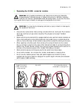


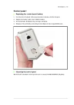

Maintenance 95
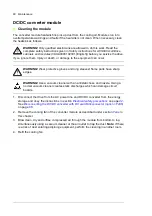
1. Disconnect the drive from the AC power line and DC/DC converter from the energy
storage and obey the instructions in section
on page
See
Disconnecting the DC/DC converter with DC switch/disconnector (F286)
on page
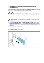
2. Open the cubicle door.
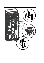
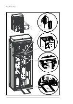
3. Undo the screws of the shroud in the upper part of the cubicle. Remove the shroud.
4. Unplug the terminal block [X30] cable on top of the module.
5. Disconnect the busbars on top of the filter module. Be careful not to drop the screws
inside the module!
C121, marine construction: See
Replacing the DC/DC converter module
.
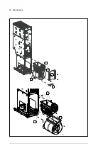
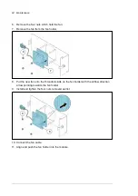
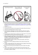
6. Remove the two screws that fasten the bottom of the module to the base of the
cabinet.
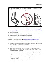
7. Install the module pull-put ramp: lift the module pull-out ramp against the cabinet base
so that the hooks of the base go into the ramp’s holes.
8. Remove the two fastening screws that fasten the top of the module to the cabinet
frame.
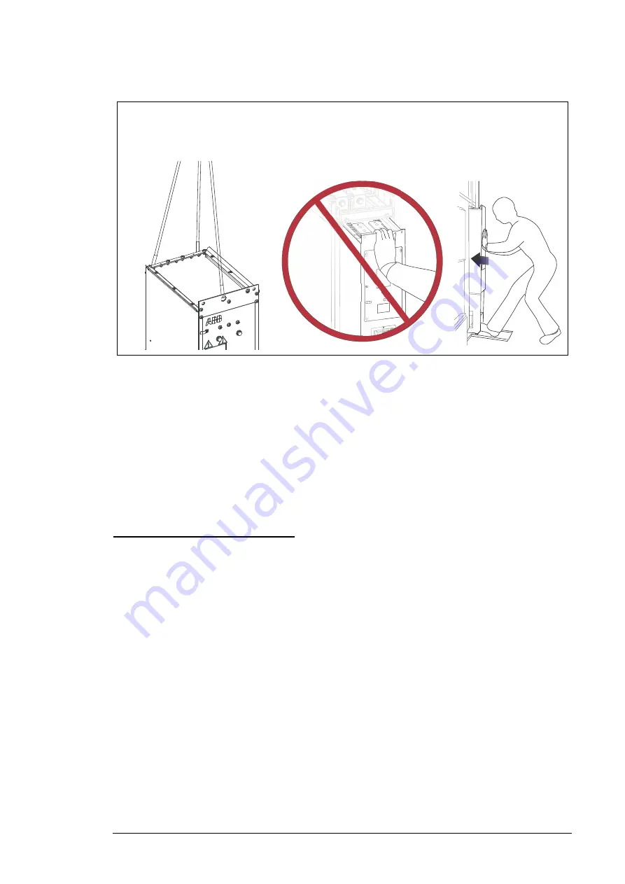
9. Pull the module carefully out of the cabinet along the ramp. While pulling on the
handle, keep a constant pressure with one foot on the base of the module to prevent
the module from falling on its back.
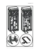
10. Replace the module: install the module in reverse order. Mind you fingers. Keep a
constant pressure with one foot on the base of the module to prevent the module from
falling on its back.
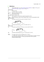
Note:
Be careful not to break the fastening screws: tighten the
fastening screws of the module to 22 N·m (16.2 lbf.ft) and fastening bolts of the DC
output busbars to 42 N·m (30.98 lbf.ft).
•
Plug the module signal wire set to the module signal connector.
•
Fasten the shrouds.
11. Remove the module pull-out ramp and close the cabinet doors.
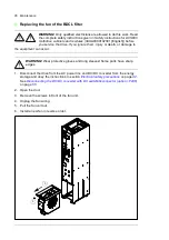
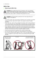
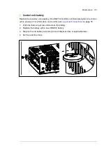
Lift the module by the upper part only
using the lifting holes at the top!
Mind your fingers! Keep fingers
away from the edges of the
front flange of the module!
Support the top and bottom
of the module while
replacing!
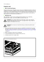
Summary of Contents for ACS880-1607
Page 1: ...ABB industrial drives Hardware manual ACS880 1607 DC DC converter units ...
Page 4: ......
Page 12: ...12 Introduction to the manual ...
Page 34: ...34 Mechanical installation ...
Page 40: ...40 Guidelines for planning electrical installation ...
Page 52: ...52 Electrical installation ...
Page 68: ...68 Start up ...
Page 80: ...80 Maintenance 7 3 4 5 6 ...
Page 82: ...82 Maintenance 3 4 5 6 7 8 9 9 ...
Page 85: ...Maintenance 85 12 Install and tighten the two screws 10 11 12 ...
Page 92: ...92 Maintenance 3 6 4 5 4 7a 7b 7b ...
Page 93: ...Maintenance 93 9 8 8 10 11 ...
Page 96: ...96 Maintenance 4 8 6 7 5 3 ...
Page 97: ...Maintenance 97 9 ...
Page 118: ...118 Dimensions Dimension drawings Frame 1 R8i bottom cable entry ...
Page 119: ...Dimensions 119 Frame 1 R8i top cable entry ...
Page 122: ...www abb com drives www abb com drivespartners 3AXD50000023644 Rev B EN 2017 01 30 Contact us ...


