


318 Parameters
76
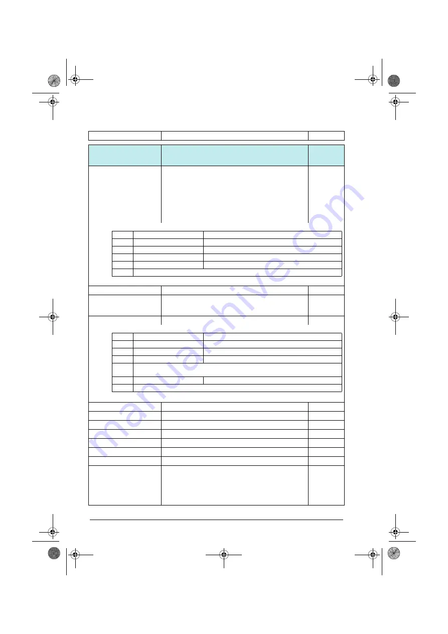
PFC (Pump and fan control) and Autochange configuration
parameters. See also section
page
Displays the running/stopped status of the PFC motors.
PFC1, PFC2, PFC3 and PFC4 always correspond to the
1st…4th motor of the PFC system. If
auxiliary PFC is set to
, PFC1
represents the motor connected to the drive and PFC2 the
first auxiliary motor (the 2nd motor of the system). If
set to
, PFC1 is the first motor, PFC2 the 2nd. The
drive can be connected to any of these motors depending on
the Autochange functionality.
-
0000h…FFFFh
Status of the PFC relay outputs.
1 = 1
Displays the status of the PFC system in text form. Provides a
quick PFC system overview, eg. if the parameter is added to
the Home view on the control panel.
-
Shows the status of pump or fan 1.
-
0000h…FFFFh
Status of pump or fan 1.
1 = 1
.
-
.
-
.
-
Selects the multi-pump/fan control (PFC) mode.
Off
PFC disabled.
0
Reserved
1
PFC
PFC enabled. One pump at a time is controlled by the drive.
The remaining pumps are direct-on-line pumps that are
started and stopped by the drive logic
The frequency (group
) / speed
(group
) reference must be
defined as PID for the PFC functionality to work properly.
2
No.
Name/Value
Description
Def/FbEq16
Bit
Name
Value
0
PFC 1 running
0 = Stop, 1 = Start
1
PFC 2 running
0 = Stop, 1 = Start
2
PFC 3 running
0 = Stop, 1 = Start
3
PFC 4 running
0 = Stop, 1 = Start
4…15
Reserved
Bit
Name
Value
0
Ready
0 = False, 1 = True
2
Running
0 = False, 1 = True
5
In PFC control
0 = False, 1 = True
1, 3,
4…10
Reserved
11
Interlocked
0 = False, 1 = True
12…15 Reserved
ACS580 FW.book Page 318 Wednesday, September 21, 2016 9:48 PM