58 Planning the electrical installation
Other regions
The disconnecting device must conform to the applicable local safety regulations.
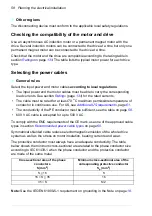
Checking the compatibility of the motor and drive
Use an asynchronous AC induction motor or a permanent magnet motor with the
drive. Several induction motors can be connected to the drive at a time but only one
permanent magnet motor can be connected to the drive at a time.
Check that the motor and the drive are compatible according to the rating table in
section
. The table lists the typical motor power for each drive
type.
Selecting the power cables
General rules
Select the input power and motor cables
according to local regulations
:
• The input power and the motor cables must be able to carry the corresponding
load currents. See section
(page
) for the rated currents.
• The cable must be rated for at least 70
°
C maximum permissible temperature of
conductor in continuous use. For US, see
page
.
• The conductivity of the PE conductor must be sufficient, see the table on page
• 600 V AC cable is accepted for up to 500 V AC.
To comply with the EMC requirements of the CE mark, use one of the approved cable
types in section
.
Symmetrical shielded cable reduces electromagnetic emission of the whole drive
system as well as the stress on motor insulation, bearing currents and wear.
The protective conductor must always have an adequate conductivity. The table
below shows the minimum cross-sectional area related to the phase conductor size
according to IEC 61439-1 when the phase conductor and the protective conductor
are made of the same metal.
Note:
See the IEC/EN 61800-5-1 requirement on grounding in the Note on page
.
Cross-sectional area of the phase
conductors
S (mm
2
)
Minimum cross-sectional area of the
corresponding protective conductor
S
p
(mm
2
)
S < 16
S
16 < S < 35
16
35 < S
S/2
Summary of Contents for ACS580-01 drives
Page 1: ...ABB general purpose drives Hardware manual ACS580 01 drives 0 75 to 250 kW...
Page 4: ......
Page 11: ...Table of contents 11 Document library on the Internet 225...
Page 12: ...12 Table of contents...
Page 72: ...72 Planning the electrical installation...
Page 79: ...Electrical installation 79 R6 R9 3 3 4...
Page 132: ...132 Maintenance and hardware diagnostics...
Page 168: ...168 Dimension drawings Frame R0 IP21 3AXD10000257110...
Page 169: ...Dimension drawings 169 Frame R0 IP55 3AXD10000341562...
Page 170: ...170 Dimension drawings Frame R1 IP21 3AXD10000257188...
Page 171: ...Dimension drawings 171 Frame R1 IP55 3AXD10000336766...
Page 172: ...172 Dimension drawings Frame R2 IP21 3AXD10000257203...
Page 173: ...Dimension drawings 173 Frame R2 IP55 3AXD10000341578...
Page 174: ...174 Dimension drawings Frame R3 IP21 3AXD10000257219...
Page 175: ...Dimension drawings 175 Frame R3 IP55 3AXD10000335424...
Page 176: ...176 Dimension drawings Frame R4 IP21 3AXD10000332430...
Page 177: ...Dimension drawings 177 Frame R4 IP55 3AXD10000427933...
Page 178: ...178 Dimension drawings Frame R5 IP21 3AXD10000412280...
Page 179: ...Dimension drawings 179 Frame R5 IP55 3AXD10000415964...
Page 180: ...180 Dimension drawings Frame R6 IP21 3AXD10000258705...
Page 181: ...Dimension drawings 181 Frame R6 IP55 3AXD10000330667...
Page 182: ...182 Dimension drawings Frame R7 IP21 3AXD10000258995...
Page 183: ...Dimension drawings 183 Frame R7 IP55 3AXD10000330932...
Page 184: ...184 Dimension drawings Frame R8 IP21 3AXD10000287670...
Page 185: ...Dimension drawings 185 Frame R8 IP55 3AXD10000332446...
Page 186: ...186 Dimension drawings Frame R9 IP21 3AXD10000287428...
Page 187: ...Dimension drawings 187 Frame R9 IP55 3AXD10000334310...
Page 188: ...188 Dimension drawings...
Page 196: ...196 Resistor braking...

