Actual signals and parameters
184
23.04
ACC
COMPENSATION
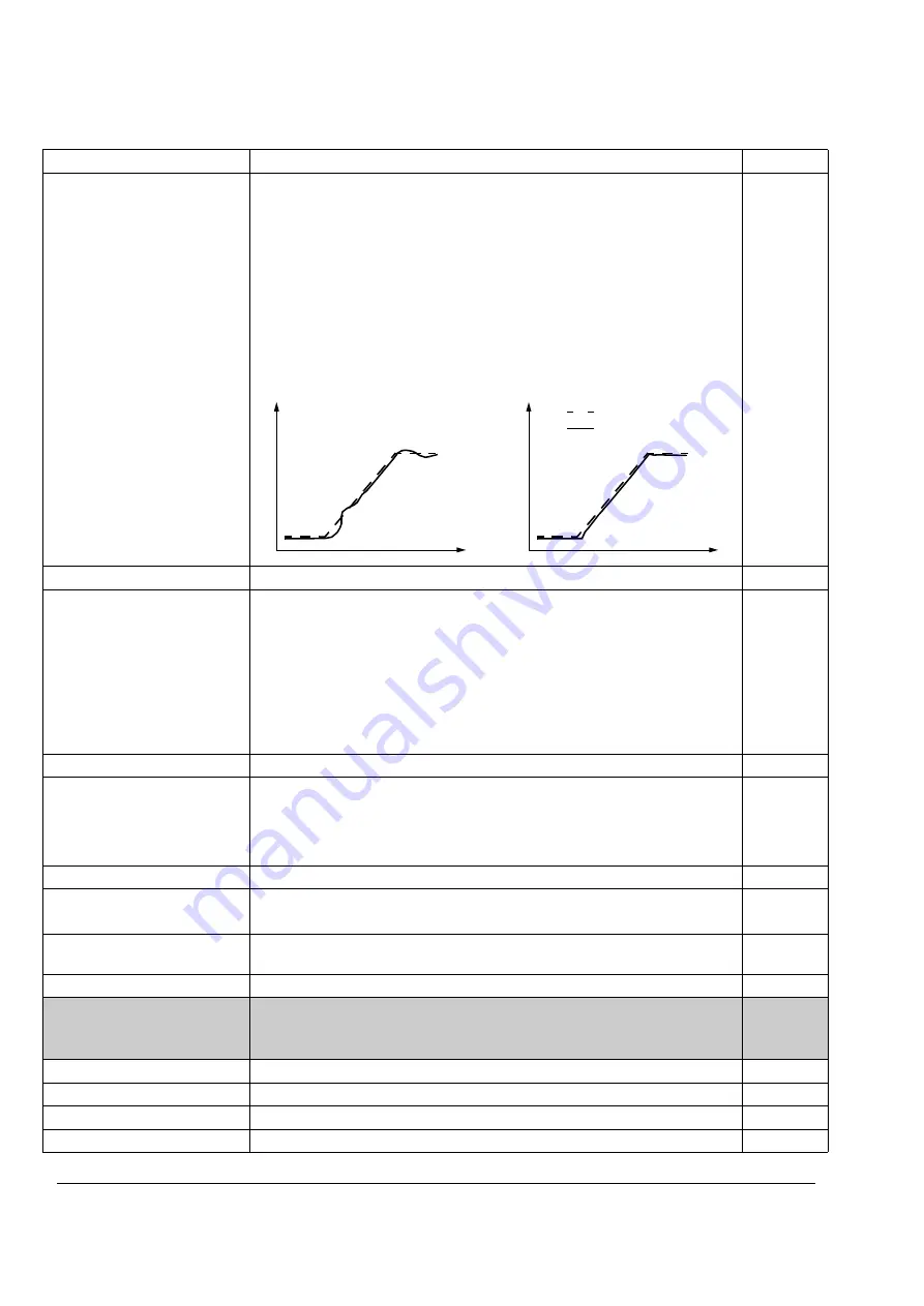
Defines the derivation time for acceleration/(deceleration) compensation. In
order to compensate inertia during acceleration a derivative of the reference is
added to the output of the speed controller. The principle of a derivative action
is described for parameter
Note:
As a general rule, set this parameter to the value between 50 … 100% of
the sum of the mechanical time constants of the motor and the driven machine.
(The speed controller Autotune Run does this automatically, see parameter
The figure below shows the speed responses when a high inertia load is
accelerated along a ramp.
0.00 … 999.98 s
Derivation time
0 … 9999
23.05
SLIP GAIN
Defines the slip gain for the motor slip compensation control. 100% means full
slip compensation; 0% means no slip compensation. The default value is
100%. Other values can be used if a static speed error is detected despite of
the full slip compensation.
Example:
1000 rpm constant speed reference is given to the drive. Despite of
the full slip compensation (SLIP GAIN = 100%), a manual tachometer
measurement from the motor axis gives a speed value of 998 rpm. The static
speed error is 1000 rpm - 998 rpm = 2 rpm. To compensate the error, the slip
gain should be increased. At the 106% gain value, no static speed error exists.
0.0 … 400.0%
Slip gain value.
0 … 400
23.06
AUTOTUNE RUN
Start automatic tuning of the speed controller. Instructions:
- Run the motor at a constant speed of 20 to 40% of the rated speed.
- Change the auto tuning parameter
Note:
The motor load must be connected to the motor.
NO
No auto tuning.
0
YES
Activates the speed controller auto tuning. Automatically reverts to NO.
65535
23.07
SP ACT FILT TIME
Defines the time constant of the actual speed filter, that is time within the actual
speed has reached 63% of the nominal speed.
0...1000000 ms
Time constant
1 = 1 ms
24 TORQUE CTRL
Torque control variables.
Visible only if Master/Follower is Active (parameter
and parameter
= DTC.
24.01
TORQ RAMP UP
Defines the torque reference ramp up time.
0.00 … 120.00 s
Time for the reference to increase from zero to the nominal motor torque.
0 … 12000
24.02
TORQ RAMP DOWN Defines the torque reference ramp down time.
0.00 … 120.00 s
Time for the reference to decrease from the nominal motor torque to zero.
0 … 12000
Index
Name/Selection
Description
FbEq
Speed reference
Actual speed
No Acceleration Compensation
Acceleration Compensation
t
t
%
%
Summary of Contents for ACS 800 Series
Page 1: ...ACS800 Firmware Manual Crane Control Program N697 ...
Page 4: ......
Page 26: ...Start up and control through the I O interface 26 ...
Page 36: ...Quick start up guide 36 ...
Page 52: ...Control panel 52 ...
Page 105: ...Program features 105 Figure Control diagram for Shaft synchronisation executed in 20 ms ...
Page 128: ...Program features 128 ...
Page 150: ...Application macros control location EXT1 EXT2 150 ...
Page 228: ...Actual signals and parameters 228 ...
Page 299: ...Adaptive Programming examples for crane control 299 ...
Page 305: ...Adaptive Programming examples for crane control 305 ...
Page 318: ...Analogue Extension Module 318 ...
Page 332: ...Additional data actual signals and parameters 332 ...
Page 334: ...DriveWindow 334 ...
Page 335: ...Control block diagrams 335 Control block diagrams ...
Page 336: ...Control block diagrams 336 ...
Page 337: ...Control block diagrams 337 ...
Page 338: ...Control block diagrams 338 ...
Page 340: ...www abb com drives www abb com drivespartners Contact us 3AFE68775230 Rev E EN 2012 09 25 ...


