


ACH550-UH User’s Manual
1-257
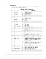
Embedded fieldbus
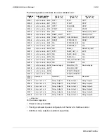
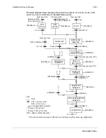
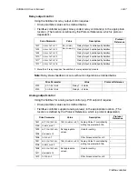
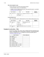
The state diagram below describes the start-stop function of
CONTROL
WORD
(CW)
and
STATUS
WORD
(SW) bits for the ABB Drives profile.
(CW xxxx xxxx xxxx x110)
MAINS OFF
Power ON
(CW Bit0=0)
(SW Bit6=1)
(SW Bit0=0)
From any state
f=0 / I=0
OFF1 (CW Bit0=0)
A
C
D
(CW Bit3=0)
(SW Bit2=0)
(SW Bit0=1)
(CW xxxx xxxx xxxx x111)
(SW Bit1=1)
(CW Bit3=1 and
(CW Bit5=0)
f=0 / I=0
(SW Bit2=1)
From any state
SWITCH-ON
INHIBITED
NOT READY
TO SWITCH ON
OPERATION
INHIBITED
READY TO
SWITCH ON
READY TO
OPERATE
OPERATION
ENABLED
C D
From any state
Emergency Off
OFF2 (CW Bit1=0)
(SW Bit4=0)
OFF2
ACTIVE
From any state
Fault
(SW Bit3=1)
FAULT
(CW Bit7=1)*
(SW Bit5=0)
Emergency Stop
OFF3 (CW Bit2=0)
SW Bit12=1)
RFG: ACCELERATOR
ENABLED
(CW Bit5=1)
(CW Bit6=0)
C
(CW Bit6=1)
(SW Bit8=1)
D
A
D
OPERATING
OFF3
ACTIVE
*This state transition also occurs if the fault is reset from any other source (e.g. digital input).
KEY
State
CW =
CONTROL
WORD
SW =
STATUS
WORD
Path described in example
I = Param. 0104
CURRENT
f = Param. 0103
OUTPUT
FREQ
RFG = Ramp Function Generator
Summary of Contents for ACH550-UH HVAC
Page 2: ......
Page 8: ...1 8 ACH550 UH User s Manual Table of contents ...
Page 32: ...1 32 ACH550 UH User s Manual Installation ...
Page 66: ...1 66 ACH550 UH User s Manual Application macros ...
Page 186: ...1 186 ACH550 UH User s Manual Parameters ...
Page 333: ...ACH550 UH User s Manual 1 333 Technical data ...


