background image

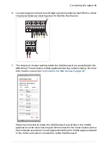
5. The information of RTD cabling inside the MACHsense-R are defined in the

ABB Ability™ Smart Sensor mobile application during commissioning. For more
information, see section

Commission the MACHsense-R (page 32)

.

Make the connections inside the MACHsense-R similar to the predefined order
set in the mobile application, otherwise there may be KPI mismatch in the
Smart Sensor portal. The default configuration for temperature sensors support
the following five RTDs:

three stator RTDs, one per phase

two bearing RTDs, one for each Drive end and Non-drive end.

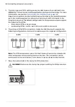
6. The wiring of RTD/BTD connections inside the MACHsense-R supports the

following configurations. Connect the cables as per the required configuration.

2-wire

3-wire

4-wire

Note: The RTD temperature sensor for MACHsense-R cannot be shared with
other temperature-measured systems or devices. The connection can be
terminated in the terminal box, from where it can be wired inside the DAU.

7.

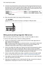
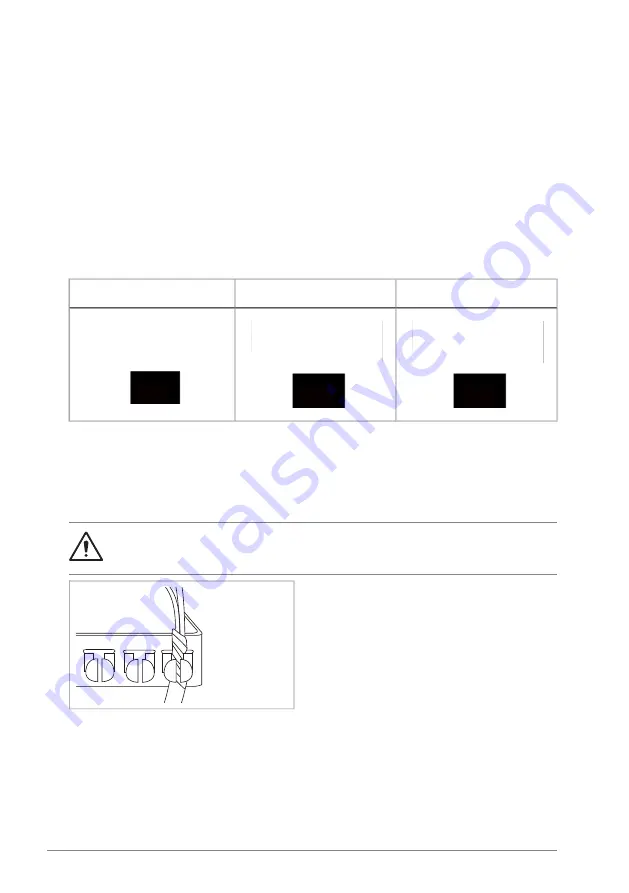
Place the cable shield in the clamp for EMI protection.

WARNING! Make sure the clamp has proper earthing for EMI protection.

60 Connecting temperature sensors

Summary of Contents for Ability MACHsense-R

Page 1: ...ABB MOTION SERVICES ABB Ability MACHsense R MSR1608 Data acquisition unit User manual...

Page 2: ......

Page 3: ...lity MACHsense R MSR1608 Data acquisition unit User manual Table of contents 1 Safety instructions 3 Getting started 4 Preparing for installation 4MSL0007 Rev A EN Original instructions EFFECTIVE 2023...

Page 4: ......

Page 5: ...Terms and abbreviations used in this manual 16 Related documents 16 Disclaimers 16 General disclaimer 17 Cybersecurity disclaimer 3 Getting started 19 Contents of this chapter 19 MACHsense R overview...

Page 6: ...ounting pads in motors with fins 40 Mount the sensors 41 Additional mounting information 6 Installing the Magnetic Field Sensor 43 Contents of this chapter 43 Examine the MFS mounting location 44 Moun...

Page 7: ...Contents of this chapter 67 Connect LAN cable 13 Technical data 69 Contents of this chapter 69 Software 69 Wi Fi 802 11 a b g n ac 70 Bluetooth 5 0 BR EDR LE 70 Mobile LTE 4G HSPA 3G 70 Connectivity 7...

Page 8: ...8...

Page 9: ...Keep the DAU in its package until you install it After unpacking protect the DAU from dust debris and moisture Handle the DAU carefully not to drop it down Use the required personal protective equipm...

Page 10: ...trical professional do not do installation or maintenance work You must be trained in and be familiar with the specific maintenance procedures and tests required for rotating electrical machines Go th...

Page 11: ...restart lockout Installing the DAU requires wiring so do not try to install when a motor or connected drive is energized Do not work on the DAU while the drive motor cable motor control cables or con...

Page 12: ...12...

Page 13: ...ABB Ability MACHsense R MSR1608 data acquisition unit Note The manual may refer to some general information about various ABB products If the information is different than the actual product supplied...

Page 14: ...re that all necessary accessories and equipment are present and correct MACHsense R order information page 24 SIM card and subscription order informa tion page 24 Only intact units can be started up S...

Page 15: ...nterface Terms and abbreviations used in this manual Explanation Term Measures the vibration or acceleration of motion Accelerometer Access Point Name is a gateway between a mobile network and an othe...

Page 16: ...uick installation and start up guide For more information about MACHsense R go to ABB website new abb com products 3BSM045701 1 For product or sales support contact support machsense abb com ABB local...

Page 17: ...r connection service as provided by ABB and instead prefers to use their own network communication solution it is Customer s sole responsibility to provide and continuously ensure a secure remote conn...

Page 18: ...18...

Page 19: ...toring hardware referred to as Data Acquisition Unit DAU which is installed on the site See the process overview shown in the below Process overview diagram page 20 The built in software within the DA...

Page 20: ...Process overview diagram 20 Getting started...

Page 21: ...gnetometer cable 10 m 7 3 x Pluggable connectors 16 way 8 Quick installation guide 9 Note The delivery package does not include SIM card You can order them separately See SIM card order information on...

Page 22: ...tion The DAU unit front panel consists of following items 1 2 3 4 5 6 ABB logo 1 QR code 2 Power on LED 3 Lock 4 Safety label 5 Designation label See description in section Designation label page 23 6...

Page 23: ...nufacturing plant YY 22 23 for 2022 2023 XXXXX Digits making the serial number unique MAC address of format XX XX XX XX XX XX where 5 XX Alpha numeric characters Year of manufacturing 6 Valid markings...

Page 24: ...ion 3BSM045708 1 1 MACHsense R three year subscription 3BSM045705 1 2 SIM card kit 3AXD50000825981 3 Standard sensors order information The DAU can operate with different analog and digital sensors Th...

Page 25: ...your own For list of materials included in the package see Package contents page 21 Power supply cable Glue LOCTITE AA 326 SIM card Activator LOCTITE SF 7649 Cable stripper Surface cleaner LOCTITE SF...

Page 26: ...26...

Page 27: ...al and local safety instructions See Safety instructions page 9 WARNING Obey the instructions described in this manual otherwise it may result in incorrect installation of the device Install the anten...

Page 28: ...card and subscription order information page 24 or contact your local ABB representative To activate and install the SIM card do the below steps 1 Scan the QR code on the ABB SIM card holder using you...

Page 29: ...O GPO00 GND GPO 24V 5V PWR OUT GND SV GND 24V GPO01 GPO02 GPO03 2 Locate the SIM card slot inside the DAU See below figure 3 To install the SIM card insert into the slot and press it until it is secur...

Page 30: ...ed in MACHsense R package in accordance with the local regulations and applicable standards To connect the supply cables inside MACHsense R do the below steps 1 Pierce the rubber membrane using a scre...

Page 31: ...ARNING Handle screwdriver carefully Keep your fingers away while piercing the rubber membrane 2 Push the cable through the rubber membrane and attach the gasket as shown in the below figure Note The b...

Page 32: ...o the below steps 1 Download the ABB Ability Smart Sensor mobile application through Google play store or the Apple App Store For China users use the ABB App store for Android ABB App store for Androi...

Page 33: ...lect ABB SIM Card option otherwise select the Manual option to enable the internet APN settings as shown in above sample screen Example APN configuration details for the Swisscom and m2m SIM cards APN...

Page 34: ...34...

Page 35: ...in only one direction so determine the best position to mount on the motor The mounting locations can differ based on the configuration For example of mounting locations see example 1 page 37 and exam...

Page 36: ...he shaft Motor Non Drive End Axial On top of the bearing housing pointing directly towards the bearing This sensor should be mounted at an angle of 90 degrees to the DE Horizontal sensor Motor Drive E...

Page 37: ...of the bearing housing pointing directly towards the bearing This sensor should be mounted at an angle of 90 degrees to the DE Horizontal sensor DE Vertical 2 On the DE of the motor pointing directly...

Page 38: ...the shaft on the top foundation of the rotating machine DE Vertical 3 On the Non Drive End NDE of the motor pointing directly to wards the bearing NDE Horizontal 4 Fix the mounting pads Before install...

Page 39: ...keep steady for 10 minutes For more information see Loctite SF 7649 page 72 Fix the triaxial mounting base Fix the triaxial mounting base or cubical structures with threaded holes or studs to mount th...

Page 40: ...he motor casing item 3 in below figure as possible mounting pad is not resting on top of the fins If it rests on top of the fins make sure the bottom of the probe is not in direct contact with the mot...

Page 41: ...inimal interfaces to avoid any loss of energy due to high frequency oscillations in the face of the interface Mount the sensors close to the bearing and pointing towards the shaft center line Select t...

Page 42: ...42...

Page 43: ...ted on the motor and MFS sensors can be installed with Y axis as the axial direction e g parallel to the motor shaft To locate the correct mounting positions on the motor consider the following points...

Page 44: ...or magnetometer is covered with a plastic case The MFS enclosure can be mounted directly on to the motor using glue To mount the MFS do the below steps 1 Remove any paint on the surface by grinding so...

Page 45: ...ow points to the NDE X axis is vertical to the motor base pointing against it Z axis points away from the motor 4 Stick the plastic enclosure on the glued motor surface and hold until the glue sets ap...

Page 46: ...46...

Page 47: ...ct a mounting location which is a non hazardous area and free of shock forces and excessive dust avoiding proximity to electrical appliances etc Make sure the selected mounting location and subsequent...

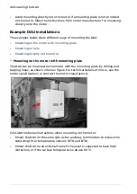
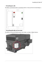
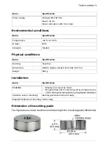
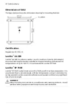
Page 48: ...with mounting plate The DAU can be mounted on the motor with the mounting plate by drilling and tapping holes as shown in below figure For technical details of motor see the motor specifications or c...

Page 49: ...on rails The DAU can be mounted on an external frame or rail as shown in below figure Mounting directly on the motor The DAU can be mounted directly on the motor as show in figure below Installing th...

Page 50: ...50...

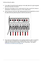
Page 51: ...cause wire strand breakage and insulation failure and result in noisy or broken connections 2 Secure the cables with cable ties or clamps to avoid them hanging loose When securing the cable leave enou...

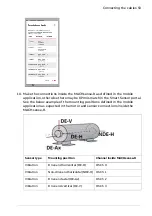
Page 52: ...reen 8 Locate the green connectors with high speed channels marked HSChxx Check the polycarbonate protecting sheet to identify the channel HSCh3 HSCh2 HSCh1 HSCh0 RTN IN 9 The sensor mounting position...

Page 53: ...unting positions defined in the mobile application as expected in the motor and sensor connections inside the MACHsense R Channel inside MACHsense R Mounting position Sensor type HS Ch 0 Drive end hor...

Page 54: ...tion and slapping Note If cables are allowed to have excessive motion it can result in cable metal and insulation fatigue The fatigue can cause wire strand breakage and insulation failure and result i...

Page 55: ...the ABB Ability Smart Sensor mobile application during commissioning For more information see section Commission the MACHsense R page 32 Make the connections inside the MACHsense R as defined in the...

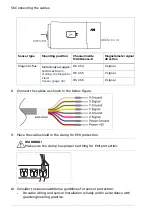
Page 56: ...Y signal HS Ch 5 Z signal HS Ch 6 8 Connect the cables as shown in the below figure 9 Place the cable shield in the clamp for EMI protection WARNING Make sure the clamp has proper earthing for EMI pro...

Page 57: ...mperature Make sure the sensor location does not hinder other operational and maintenance measures Install the mounting hardware or sensors correctly on the application to maximize frequency response...

Page 58: ...58...

Page 59: ...side MACHsense R do the below steps 1 Pierce in the rubber membrane using a screwdriver to push through a cable sensor For instructions see Using the rubber membrane plate page 31 2 Push cables throug...

Page 60: ...o bearing RTDs one for each Drive end and Non drive end 6 The wiring of RTD BTD connections inside the MACHsense R supports the following configurations Connect the cables as per the required configur...

Page 61: ...connect with the serial RS485 terminal inside MACHsense R do the below steps 1 Pierce the rubber membrane using a screwdriver to push through a serial cable For instructions see Using the rubber membr...

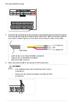
Page 62: ...echanism Make sure proper polarity as shown in below figure is used when connecting the wires to the DAU positive line to terminal RS485A marked A negative line to RS485B marked B ground to GND termin...

Page 63: ...ction page 63 GPI interface supports input voltage up to 24 V and pulse rate of 100Hz For more information see GPI connection page 64 GPO connection To connect the GPO terminal inside MACHsense R do t...

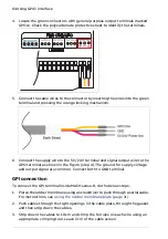
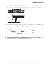
Page 64: ...to the GPO terminal as shown in the figure step 4 The ground for supply voltage and output signal are common Connect both to GND terminal GPI connection To connect the GPI terminal inside MACHsense R...

Page 65: ...S485 GPI03 GPI02 GPI01 PWR OUT RS485 GND A B GPI00 GND GPI GND SV GND 24V NC 5 Connect the cable wires to the connector by inserting the wires into the green terminal and pressing the orange locking m...

Page 66: ...66...

Page 67: ...the LAN cable do the below steps 1 Pierce and make a hole in the rubber membrane using a screwdriver to push through the LAN cable without RJ45 plug For instructions see Using the rubber membrane plat...

Page 68: ...tivity over the Ethernet interface contact your IT support team for information of the IP assignment policy The internet connectivity can be configured using the ABB Ability Smart Sensor mobile applic...

Page 69: ...ribution Wi Fi 802 11 a b g n ac Specification Name 2 4 GHz and 5 GHz Frequency Depending on modulation Tx power max 9 5 19 5 dBm for 2 4 GHz 8 17 dBm for 5 GHz Depending on modulation Rx sensitivity...

Page 70: ...5 dBm Tx power max LTE 39 25 dBm GSM 102 dBm Rx sensitivity LTE 97 3 98 dBm Omni directional dipole external SMA peak gain 3 dBi Antenna Mini SIM 1 x SIM slot SIM Connectivity Specification Name LAN 1...

Page 71: ...h x Height x Depth 313 x 240 x 157 mm Dimensions 500 g Weight Installation Specification Name Directly on or near the motor On separating rails if mounting surface temperature is 60 C during normal op...

Page 72: ...of up to 120 C It is activated with Loctite SF 7649 Loctite SF 7649 Loctite SF 7649 is also known as Loctite 7649 used for surface preparation It is an activator that is solvent based with low tempera...

Page 73: ...motion data and advisory services condition monitoring for powertrains Product training For information on ABB product training navigate to new abb com service training Providing feedback on ABB manu...

Page 74: ...www abb com motion services 4MSL0007A Copyright 2023 ABB All rights reserved Specifications subject to change without notice 4MSL0007 Rev A EN 2023 12 15...

Reviews: