Connection, installation / mounting
Product manual 2CKA001473B9726
│17
6.3
Circuit diagrams
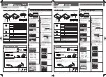
Fig. 3:
Electrical connection
[1] DC power jack
[2] USB-Port (for future functional enhancements)
[3] USB-Port (for future functional enhancements)
[4] RJ connector (RJ45)
[5] External antenna
[1] Wired free@home bus
[2] Alternative power input
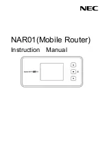
Fig. 4:
Backside of device
1
2
3
4
5
1
2