


4
4
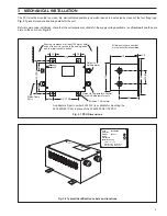
ELECTRICAL INSTALLATION
or
1–
+2
C501
4 –
1+
8 –
3 –
2+
-
+
Power Supply Unit
4234600/601
Katharometer Types
6515
6517
6518
6520
6522
6524
7 +
-
+
mA o/p
10V o/p
For temperature controlled
katharometer block type
6518, 6520, 6524
Mains in
4234 600 – 230 V a.c.
or
4234 601 – 115 V a.c.
4689 Display
TBB
+12
TBB
10–
or
28–
+29
C351
or
1–
+2
Datum
L150
Commander Series
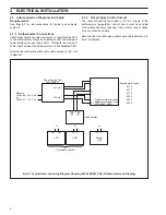
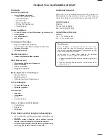
Fig. 4.1 Typical Interconnecting Diagram Showing 4234 600/601 PSU, Katharometer and Displays
4.1
Interconnection Diagrams and Cable
Requirements
See Fig. 4.1 for interconnections for typical gas analysis
systems.
4.1.1
Katharometer Connections
Cable connecting the constant current d.c. supply from the PSU
to the katharometer should be selected so that the maximum
cable resistance is less than 2 ohms. This limits the maximum
cable length between the katharometer and its associated PSU.
Note that the cable gland will accept a cable between 5 to 9 mm
in diameter.
4.1.2
Temperature Control Circuit
The cable connecting the auxiliary 10 V d.c. supply to the
katharometer temperature control circuit must have cable
conductance capable of passing 1 amp without undue voltage
drop or excessive heating.
Note also that the cable gland will accept a cable between 5 to
9 mm in diameter.


