3
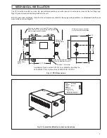
Fig. 3.1 PSU Dimensions
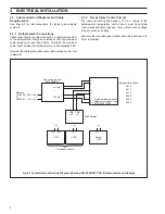
Fig. 3.2 Typical Identification Labels and locations
3
MECHANICAL INSTALLATION
A B B L i m i t e d
Oldends Lane, Stonehouse,
Glos. England GL10 3TA
Code
4234/600XX
Serial No
Voltage
230 Vac
Watts
Year Manuf.
Manufactured by:
N4006
✔
The PSU must be mounted in a clean, dry, well ventilated position (on a wall or panel) in a safe area by means of the four fixing lugs.
Fig. 3.1 gives dimensions and fixing details for the unit.
Before commencing installation, check that the unit supplied is suitable for the supply voltage available – see Section 2 and the data
plate on the unit cover, Fig. 3.2.
140 CTRS
110 CTRS
170
111
120
All holes 7.0 diameter
160
83
20
20
30
30
30
60 DIM
Ensure a clearance of at least 100 mm at both
ends of the unit for acces to the cable glands
and to minimise cable bends.
Mains Cable
Entry
Output to Temperature Control
Circuit in Katharometer only
Output to
Katharometer
3.0
An adaptor kit (part number 4234 519) is available for mounting the
4234 600/601 PSU in place of the 004235 000/01/02 PSU.
All dimensions are nominal
mm unless otherwise stated.

