


P. 33 - Chap. 6 Handling and installation
G
B
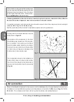
In particular, hoses which are not perfectly secured may cause severe injuries due to unpredictable move-
ments. Make sure that the hose ends are firmly secured before pressurizing them.
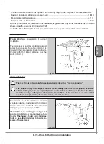
The condensate drain must be connected to a collection system with a suitable pipe as established by local
regulations for the disposal of polluting substances.
6.4
Electrical connection
The electrical power system must include a main circuit breaker with line sectioning function that can be
padlocked, with fuses or thermal cut-out suitably rated according to the characteristics of the machine, and a
device against accidental contacts in order to protect personnel.
The setting of the safety devices and the rating of the line circuit breaker must comply with the indications
provided in the table of paragraph 4.6.
The circuit breaker must be positioned close to the machine. Comply scrupulously with specific local accident
prevention regulations.
The power cables must have an adequate cross-section area for current take-off (see the table in paragraph
4.6).
Electrical systems must comply with the rules of good workmanship and be installed by a qualified electrician
who must check the efficiency of the earthing system.
The power cable must be secured in the specific glands and the electrical panel must be tightly closed to
achieve the prescribed IP44 protection rating.
Connect the machine only to type-approved sockets. The sockets must be earthed and tested.
Have correct fastening of the electrical cables of the various components checked regularly by qualified
personnel.
Chapter 12 contains the operational and layout wiring diagrams of the auxiliary and power circuits. The same
diagrams are also shown inside the machine control box.
6.5
Configuration for remote control
This paragraph describes how to configure the compressor for remote starting and stopping of this.
Alternatively, it is also possible to check operating mode (load / unload) or both functions by means
of an external control logic.
The operations described must be carried out by a qualified electrician.
To configure the remote control of the compressor, first of all remove the jumper between terminals 3 and 38
of the terminal strip inside the electrical cabinet (see wiring diagrams in Chapter 12)
One or two switches must be installed as described below according to whether only switching ON/OFF
and/or operating mode is to be controlled.
Remote control ON/OFF
(see paragraph 7.4.2.3 - Remote control type)
The switch must be connected to the following terminals after removing the jumper:
3
digital INPUT common terminal
Summary of Contents for GENESIS Series
Page 1: ...GENESIS FORMULA MODULO 5 5 15 kW USE AND MAINTENANCE HANDBOOK GB...
Page 2: ......
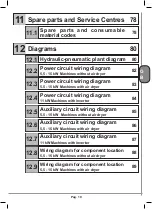
Page 82: ...P 80 Chap 12 Diagrams G B 12 Diagrams Hydraulic pneumatic plant diagram 12 1...
Page 85: ...P 83 Chap 12 Diagrams G B Power circuit wiring diagram 5 5 15 kW Machines with air dryer 12 3...
Page 86: ...P 84 Chap 12 Diagrams G B Power circuit wiring diagram 11 kW Machines with inverter 12 4...
Page 89: ...P 87 Chap 12 Diagrams G B Auxiliary circuit wiring diagram 11 kW Machines with inverter 12 7...


