Customizing the mission
When the default mission does not meet your requirements, you can of course change it to fit your needs. To do so
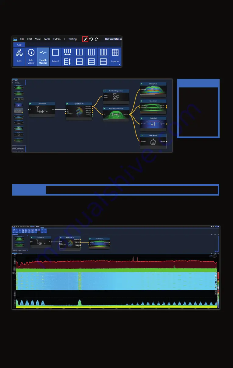
open the blockgraph editor by clicking on the pen button at the top of the application window:
That will open the blockgraph editor in a new window section:
In the blockgraph editor you can add, remove or rearrange blocks to measure and analyze data. This is done using a
drag & drop interface and connecting the in- and outputs of different blocks. Different blocks support different
datatypes indicated by the colors and labels of the connectors. Connections can only be established between
blocks supporting compatible data types (e.g. it is not possible to connect an IQ output to a Spectra input). Remo-
ving blocks is achieved by selecting the block and pressing the “Delete” key on the keyboard.
Please refer to the RTSA-Suite PRO manual at
https://aaronia.com/rtsa-manual/
for details.
Mission examples
Some examples for alternative mission configurations:
One of the simplest missions possible:
The mission begins with a calibration block on the left in the blockgraph editor (see picture above). To specify which
cable, antenna and/or other RF equipment is connected to the SPECTRAN
®
V6, so the RTSA-Suite PRO can adjust
the data for the generated gain or loss. The Calibration block output is connected to the RF input of a SPECTRAN
V6 block to control the device. And finally, the Spectra 1 output of the SPECTRAN V6 block sends the measured data
to a ComboView block to provide a combined display of spectrum, histogram and waterfall.
This example uses the Spectra output of the SPECTRAN V6 block instead of passing the IQ data through the IQ Power
Spectrum block. It simplifies the mission configuration at the cost of less influence on the FFT parameters used.
Note
The window will
likely be opened on
the left side of the
application window
and therefore be too
small to display all
contents shown
above. F5 rearran-
ges the elements
automatically.
Note
It is not possible to manually reposition elements in the blockgraph.
Drag the blocks into the editor and
connect the inputs to the fitting outputs, all by drag'n'drop.


