- -
10
3. Before Using
3.1. Site Selection
The hydraulic single post
hoist
is designed only for indoor use. Application in a room with
explosion hazard is not permitted. Setting in a wet place, a car wash center for instance,
is forbidden.
3.2. Surface Condition
The hydraulic single post
hoist
should be installed on level ground.
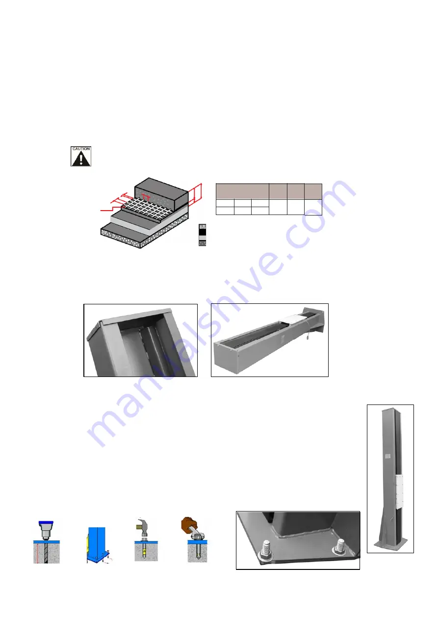
The foundation must be 6” (150mm) minimum thickness concrete, with a minimum
compressive strength of
3
,000 psi, reinforced with steel bar
Failure
to
accomplish the foundation requirement may cause the
hoist
instability
or personal injury. Installing on asphalt, soft clay floor or near the expansion
gap is prohibited.
3.3. Installation Instruction
1.
Unpack the column and other parts.
A.
Mount
the top cover o
n
the column.
B.
Mount on the curtain
to both top and bottom of the column
.
Fig. 1-A
Fig. 1-B
2.
Fix the column & lifting frame
A. Fix the column
Stand
the column
upright
and fix
to the
the ground with
supplied
(8) eight
M20 x 140 long
anchor
bolt
s.
1.
Using the base plate as a template, use a masonary drill to drill the
holes.
2.
Remove thoroughly the debris and dust in holes and ascertain that the
post stay right upon the circle previously marked by chalk.
NOTE: Torque all anchor bolts to 120 ft lbs.
Fig. 2-A-1
Fig. 2-A-2
FOUNDATION D
,
MENSIONS
IN
0
M
QUALITY OF
CONCRETE
MIN.
PRESSURE
RESISTANCE
OF SURFACE
MAX.
REACTION ON
EACH
BEARING
POINT
Length
Width
Thickness
25MPA
425
Kg/cm
2
0.9
Kg/cm
2
00
00
50
)
REINFORC
('0(6+
&203$&7('62,/
GRAVEL SHEETING
PP
[PP
)0HVK
50
PP
PP
PP
03$5(,1)25&('&21&5(7(
F i g . 2 - A -
3
Summary of Contents for AutoLift AL-167262
Page 7: ... 7 Fig 01 ...
Page 9: ...2 4Circuit Diagram 9 ...
Page 10: ......
Page 14: ......
Page 19: ... 17 6 Parts Drawing ...
Page 20: ... 18 ...
Page 21: ... 19 ...


