44
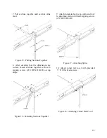
11. Attach the base splice on inside of unit
using self-tapping screws (#10 HEX HEAD)
Figure 19 - Attaching Base Splice
Splice should have 1/8” thick neoprene
preinstalled on one side.
Module Disassembly
1. Remove base splice from inside of the
unit and remove the top corner rail cover
(see Assembly Steps 10 and 11).
2. Remove screws from the integrated splice
on walls and roof (see Assembly Step 9).
3. Remove 3 end screws from top angle on
both sides of the unit (see Assembly Step 8).
4. Remove bolts connecting the two sections
at the base rail. If the sections are to be lifted
the lifting lugs must be re-attached to each
section (see Assembly Steps 3 and 5).
5. Pull one section straight back from the
other until all parts have cleared the other
section.
Note:
When re-assembling sections be sure
that all gaskets are in place. It is the
contractor’s responsibility to seal all field-
split sections.
Spring Isolator Adjustment
AAON M3 Series air handling units are
equipped with spring isolators in all blower
sections for vibration attenuation.
Prior to unit shipment the isolators are set in
the lock down position and the blower
section deck is resting on a wood base to
protect the unit during transit.
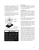
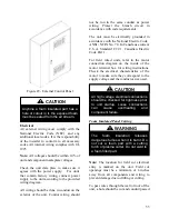
Figure 20 - Blower Spring Isolator
Once the unit is set into place it is important
that all of the isolators are adjusted out of
the shipping position and the shipping
material is discarded before the unit is put
into operation.
Removing modules that are too small
could result in injury and damage to
equipment as the module could tip
over. All sections should have a
minimum length at least equal to the
exterior unit height.
WARNING
Vibration spring isolators MUST BE
adjusted from the shipping position
prior to unit start up.
CAUTION
Summary of Contents for M3 Series
Page 53: ...53 Figure 28 Example Blow Through AAONEcat32 Rating Sheet ...
Page 73: ...73 ...
Page 74: ...74 ...
Page 75: ...75 ...

