27
5.
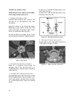
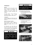
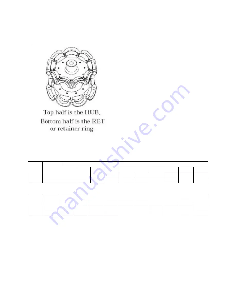
Determine whether the pin is in the HUB
or RET
Figure 12 - Fan HUB and RET Castings
6.
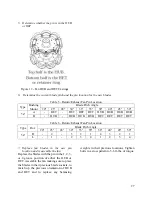
Determine the current blade pitch and the pin location for the new blades
Table 5 - Return/Exhaust Fan Pin Location
Type
Bushing
Mount
Blade Pitch Angle
20°
25°
28°
30°
33°
35°
38°
40°
45°
50°
5Z
A
-
RET
-
RET
RET
RET
HUB HUB HUB HUB
B
-
HUB
-
HUB HUB HUB
RET
RET
RET
RET
Table 6 - Return/Exhaust Fan Pin Location
Type
Rot.
Blade Pitch Angle
20°
25°
28°
30°
33°
35°
38°
40°
45°
50°
5Z
R
-
4
-
3
2
1
4
3
2
1
L
-
1
-
2
3
4
1
2
3
4
7.
Replace fan blades in the new pin
location and reassemble the fan
Replace the blades with the pin in the 1, 2, 3,
or 4 groove position of either the HUB or
RET. Assemble the fan making sure to place
the blades in their previous blade sockets, to
match up the previous orientation of HUB
and RET and to replace any balancing
weights in their previous locations. Tighten
bolts in a cross pattern to 5-6 ft-lbs. of torque.
Summary of Contents for LN Series
Page 49: ...49 ...
Page 50: ...50 ...
Page 57: ...57 Pressure Temperature Limits Flo Trex Cross Section ...
Page 62: ......


