background image


14 

General Information 

 
AAON LN Series chillers are complete self-
contained  liquid  chilling  units.  They  are 
assembled,  wired,  charged  and  run-tested. 
Models 

are 

available 

for 

air-cooled 

applications.  Chiller  primary  pumping 
packages are available as optional features. 


Codes and Ordinances 

LN  Series  units  have  been  tested  and 
certified,  by  ETL,  in  accordance  with  UL 
Safety Standard 1995/CSA C22.2 No. 236. 
 
System  should  be  sized  in  accordance  with 
the 

American 

Society 

of 

Heating, 

Refrigeration 

and 

Air 

Conditioning 

Engineers Handbook.  
 
Installation of LN Series units must conform 
to  the  ICC  standards  of  the  International 
Mechanical Code, the International Building 
Code,  and  local  building,  plumbing  and 
waste  water  codes.  All  appliances  must  be 
electrically  grounded  in  accordance  with 
local codes, or in the absence of local codes, 
the 

current 

National 

Electric 

Code, 

ANSI/NFPA  70  or  the  current  Canadian 
Electrical Code CSA C22.1. 


Receiving Unit 

When  received,  the  unit  should  be  checked 
for  damage  that  might  have  occurred  in 
transit. If damage is found it should be noted 
on  the  carrier’s  Freight  Bill.  A  request  for 
inspection by carrier’s agent should be made 
in  writing  at  once.  Nameplate  should  be 
checked to ensure the correct model sizes and 
voltages have been received to match the job 
requirements. 
 
If  repairs  must  be  made  to  damaged  goods, 
then the factory should be notified before any 
repair  action is  taken in  order to  protect  the 
warranty.    Certain  equipment  alteration, 
repair,  and  manipulation  of  equipment 
without the manufacturer’s consent may void 
the  product  warranty.    Contact  AAON 
Technical  Support  for  assistance  with 


Improper 

installation, 

adjustment, 

alteration, service or maintenance can 
cause  property  damage,  personal 
injury  or  loss  of  life.  Startup  and 
service  must  be  performed  by  a 
Factory Trained Service Technician.  


WARNING


The  Clean  Air  Act  of  1990  bans  the 
intentional venting of refrigerant as of 
July  1,  1992.  Approved  methods  of 
recovery,  recycling,  or  reclaiming 
must be followed. 


CAUTION 


Coils  and  sheet  metal  surfaces 
present  sharp  edges  and  care  must 
be 

taken 

when 

working 

with 

equipment. 


Failure  to  observe  the  following 
instructions  will  result  in  premature 
failure  of  your  system  and  possible 
voiding of the warranty. 


WARNING


WARNING


Summary of Contents for LN Series

Page 1: ... property damage A copy of this IOM should be kept with the unit Do not store gasoline or other flammable vapors and liquids in the vicinity of this or any other appliance WHAT TO DO IF YOU SMELL GAS Do not try to light any appliance Do not touch any electrical switch do not use any phone in your building Leave the building immediately Immediately call you gas supplier from a phone remote from the...

Page 2: ...peration 22 Electrical 22 Variable Speed Compressors 24 Axial Flow Condenser Fans 26 General 29 Compressors 29 Refrigerant Suction Line Filter 29 Suction Filter Removal Instructions 29 Adjusting Refrigerant Charge 30 Lubrication 33 Air Cooled Condenser 33 Brazed Plate Heat Exchanger Cleaning 33 E Coated Coil Cleaning 33 Microchannel Coil Cleaning 36 Service 38 Replacement Parts 38 AAON Technical S...

Page 3: ...igerant Temperature Pressure Chart 32 Figures Figure 1 LN Base 18 Figure 2 Curb Mounting with Dimensions 19 Figure 3 Steel Mounting Rail with Dimensions 19 Figure 4 Lifting Points 19 Figure 5 Lifting Detail of a 45 60 ton Unit 20 Figure 6 Lifting Detail of a 75 140 ton Unit 20 Figure 7 Factory Supplied End Flashings 21 Figure 8 Front View of Utility Entry and Power Switch from Control Compartment ...

Page 4: ...Brownout Protection Environmentally Friendly R 410A Refrigerant Installation and Maintenance Run Test Report and Installation Manuals Included in Controls Compartment Color Coded Wiring Diagrams Sight Glass Compressors include Rubber Isolation Mounts Vestibule Electric Heating in Service Compartment Compressor Isolation Valves Convenience Outlet Non fused Disconnect Thermometers Pressure Gauges Sy...

Page 5: ...o prevent actions that may result in equipment damage property damage or personal injury WARNING Warning statements are given to prevent actions that could result in equipment damage property damage personal injury or death DANGER Danger statements are given to prevent actions that will result in equipment damage property damage severe personal injury or death QUALIFIED INSTALLER Improper installa...

Page 6: ...f the equipment it may be necessary to work with live electrical components Only a qualified licensed electrician or individual properly trained in handling live electrical components shall perform these tasks Standard NFPA 70E an OSHA regulation requiring an Arc Flash Boundary to be field established and marked for identification of where appropriate Personal Protective Equipment PPE be worn shou...

Page 7: ...bolts requiring tooled access If you do not replace the shipping hardware with a pad lock always re install the nut bolt after closing the door CAUTION Rotation must be checked on all MOTORS AND COMPRESSORS of 3 phase units at startup by a qualified service technician Scroll compressors are directional and can be damaged if rotated in the wrong direction Compressor rotation must be checked using s...

Page 8: ...e substances only in accordance with the manufacturer s usage instructions Failure to follow instructions may result in equipment damage injury or death WARNING Do not clean DX refrigerant coils with hot water or steam The use of hot water or steam on refrigerant coils will cause high pressure inside the coil tubing and damage to the coil CAUTION Polyolester POE and Polyvinylether PVE oils are two...

Page 9: ...2 230V 3Φ 60Hz 3 460V 3Φ 60Hz 4 575V 3Φ 60Hz 8 208V 3Φ 60Hz A1 COMPRESSOR STYLE F R 410A Tandem VFD Compatible Scroll Compressor A2 CONDENSER STYLE A Air Cooled Microchannel Condenser A3 EVAPORATOR CONFIGURATION A Standard Brazed Plate Constant Flow B Oversized Brazed Plate Constant Flow C Standard Shell Tube Constant Flow D Oversized Shell Tube Constant Flow A4 COATING 0 Standard E Polymer E Coat...

Page 10: ... High Eff Motors D 1 Pump VFD High Eff Motor E 1 Dual Pump 2 VFD s High Eff Motors K 1 Pump Field Installed VFD High Eff Motor L 1 Dual Pump 2 Field Installed VFD s High Eff Motors 3B BUILDING PUMP SERIES AND RPM 0 No Building Pumps A 4360 1 170 nominal rpm B 4360 1 760 nominal rpm C 4360 3 520 nominal rpm D 4380 1 170 nominal rpm E 4380 1 760 nominal rpm F 4380 3 520 nominal rpm K 4382 1 170 nomi...

Page 11: ...BLANK 0 Standard 5A BLANK 0 Standard 5B BLANK 0 Standard 5C BLANK 0 Standard 5D BLANK 0 Standard 6 REFRIGERATION OPTIONS 0 Standard A Hot Gas Bypass on Non Variable Capacity Circuits B Hot Gas Bypass All Circuits 7 REFRIGERATION ACCESSORIES 0 Standard A Sight Glass B Compressor Isolation Valves C Option A B 8A UNIT DISCONNECT TYPE 0 Standard Single Point Power Block A Single Point Power Non fused ...

Page 12: ... BLANK 0 Standard 12 VESTIBULE ACCESSORIES 0 Standard C Vestibule Heating Electric 13 MAINTENANCE ACCESSORIES 0 Standard A 115VAC Convenience Outlet Factory Wired B 115VAC Convenience Outlet Field Wired C Service Lights F Options A C J Options B C 14 BLANK 0 Standard 15 CODE OPTIONS 0 Standard ETL U S A Listing A Chicago Code B ETL U S A Canada Listing 16 SHIPPING SPLITS 0 One Piece Unit 17 AIR CO...

Page 13: ...dard 26D BLANK 0 Standard 26E BLANK 0 Standard 26F BLANK 0 Standard 27 BLANK 0 Standard 28 BLANK 0 Standard 29 BLANK 0 Standard 30 BLANK 0 Standard 31 BLANK 0 Standard 32 BLANK 0 Standard 33 WARRANTY 0 Standard Warranty D Compressor Warranty Years 2 5 34 CABINET MATERIAL 0 Standard Double Wall R 13 Foam Insulation 35 PAINT SPECIAL PRICING AUTHORIZATIONS B Premium AAON Gray Paint Exterior E Premium...

Page 14: ...If damage is found it should be noted on the carrier s Freight Bill A request for inspection by carrier s agent should be made in writing at once Nameplate should be checked to ensure the correct model sizes and voltages have been received to match the job requirements If repairs must be made to damaged goods then the factory should be notified before any repair action is taken in order to protect...

Page 15: ... any liquid accumulation out of the compressor before it is required to run Rotation must be checked on all MOTORS AND COMPRESSORS of three phase units All motors to include and not be limited to pump motors and condenser fan motors should all be checked by a qualified service technician at startup and any wiring alteration should only be made at the unit power connection CAUTION Scroll compressor...

Page 16: ...r normal sub cooling and superheat See the air cooled condenser sections in this manual for specific details Chiller Primary Pumping Primary pumping uses a single pump to move water or glycol through the chiller barrel and back to the building This pumping package provides a constant or variable flow of water to the system The pump is activated whenever the chiller is given a run signal Water ente...

Page 17: ...and If the controls do not recognize flow in 60 seconds the second pump will be activated and an alarm signal will be generated If the second pump does not activate the cooling will be locked out See appendix for additional information Pressure Gauges and Thermometers Pressure gauges and thermometers are available as a factory installed option Thermometers are installed on the inlet and outlet of ...

Page 18: ...llation Make openings in the roof decking large enough to allow for water piping electrical penetrations and workspace only Do not make openings larger than necessary Set the curb to coincide with the openings Make sure curb is level If the LN is installed on a curb use a curb cap for the open area under the condenser section Unit specific curb drawing is included with job submittal See SMACNA Arc...

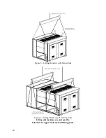
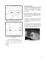
Page 19: ...nd Figure 6 for additional information Before lifting unit be sure that all shipping material has been removed from unit Secure hooks and cables at all lifting points lugs provided on the unit Hoist unit to a point directly above the curb or mounting rail Be sure that the gasket material has been applied to the curb or mounting rail Carefully lower and align unit with utility and duct openings Low...

Page 20: ...20 Figure 5 Lifting Detail of a 45 60 ton Unit Figure 6 Lifting Detail of a 75 140 ton Unit Lifting slot locations are unit specific Unit must be rigged at all marked lifting points ...

Page 21: ...unit allows the unit to set firmly on the trailer deck Sheet metal flashings are shipped loose with the unit and once the unit is set into place the flashings must be installed on each end of the unit to complete the finished seal at the base The flashings are unit specific and designed to cover the slot at each end of the unit to prevent water run off into the curb Failure to attach and seal the ...

Page 22: ... rating Supply conductors must be rated a minimum of 167 F 75 C Route power and control wiring separately through the utility entry Do not run power and signal wires in the same conduit Protect the branch circuit in accordance with code requirements The unit must be electrically grounded in accordance with local codes or in the absence of local codes the current National Electric Code ANSI NFPA 70...

Page 23: ...y factory installed wiring must be replaced use a minimum 221 F 105 C type AWM insulated conductors Supply voltage must be within the min max range shown on the unit nameplate Available short circuit current should not exceed the short circuit current rating SCCR shown on the unit nameplate Three phase voltage imbalance will cause motor overheating and premature failure The maximum allowable imbal...

Page 24: ...able Speed Compressor VFD Frequency Range Model LN Compressor VFD Range Hz 208V 230V 460V and 575V Units 045 055 060 45 65Hz 075 45 70Hz 095 105 120 35 60 Hz 140 35 65 Hz No variable speed compressor shall operate below 35 Hz Operating variable speed compressors outside the frequency range specified in this manual voids all warranties and may result in compressor failure CAUTION Rotation must be c...

Page 25: ...e compressors to confirm that all are operating within tolerance While performing the check use the startup form to record observations of compressor amps and refrigerant pressures When all is running properly place the controller in the Run mode and observe the system until it reaches a steady state of operation Note For more information on programming the controller refer to the MCS Controller m...

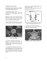
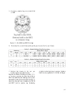
Page 26: ... direction of rotation Right R is clockwise when facing the discharge side of the fan and Left L is counterclockwise when facing the discharge side of the fan 3 Determine the bushing mount location The bushing mount is the center section of the hub through which the fan is mounted to the shaft and typically contains either setscrews or a center tapered hole where the bushing inserts Location A is ...

Page 27: ...le 6 Return Exhaust Fan Pin Location Type Rot Blade Pitch Angle 20 25 28 30 33 35 38 40 45 50 5Z R 4 3 2 1 4 3 2 1 L 1 2 3 4 1 2 3 4 7 Replace fan blades in the new pin location and reassemble the fan Replace the blades with the pin in the 1 2 3 or 4 groove position of either the HUB or RET Assemble the fan making sure to place the blades in their previous blade sockets to match up the previous or...

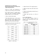
Page 28: ...he rotation of the blade 3 Replace the pitch insert in the blade root with an insert of the desired pitch Figure 13 Pitch Insert 4 Replace blades to their original location 5 Replace all nuts bolts and washers on the fan hub 6 Replace retaining plates and center boss to original location 7 Tighten nuts and bolts to 14 ft lbs of torque Fan Assembly Bushings The fan assembly bushings should be tight...

Page 29: ...le core suction filters are provided with pressure taps and shutoff valves for isolation when removing the filter For safety purposes a service manifold must be attached prior to filter maintenance Suction Filter Removal Instructions 1 Shut down operation of the unit 2 Close both shut off valves to isolate the suction filter 3 Reclaim the refrigerant from the suction filter section 4 Remove the bo...

Page 30: ...evaporator superheat Refer to Table 8 when determining the proper sub cooling For units equipped with low ambient 0 F option see the special charging instructions at the end of this section Checking Liquid Sub cooling Measure the temperature of the liquid line as it leaves the condenser coil Read the gauge pressure at the liquid line close to the point where the temperature was taken You must use ...

Page 31: ...able Refrigeration Circuit Values Air Cooled Chiller with Scroll Compressors Sub Cooling2 12 18 F Superheat1 10 15 F 1 One compressor running in tandem 2 Two compressors running in tandem Adjusting Sub cooling and Superheat Temperatures The system is overcharged if the sub cooling temperature is too high and the evaporator is fully loaded low loads on the evaporator result in increased sub cooling...

Page 32: ... 96 8 60 169 6 90 273 5 120 416 9 150 611 9 31 98 8 61 172 5 91 277 6 121 422 5 32 100 9 62 175 4 92 281 7 122 428 2 33 102 9 63 178 4 93 285 9 123 433 9 34 105 0 64 181 5 94 290 1 124 439 6 35 107 1 65 184 5 95 294 4 125 445 4 36 109 2 66 187 6 96 298 7 126 451 3 37 111 4 67 190 7 97 303 0 127 457 3 38 113 6 68 193 9 98 307 5 128 463 2 39 115 8 69 197 1 99 311 9 129 469 3 40 118 1 70 200 4 100 31...

Page 33: ...a tank with weak acid 5 phosphoric acid H3PO4 or if the exchanger is frequently cleaned 5 oxalic acid H2C2O4 Pump the cleaning liquid through the exchanger For optimum cleaning the cleaning solution flow rate should be a minimum of 1 5 times the normal flow rate preferably in a back flush mode After cleaning the heat exchanger must be rinsed with clean water A solution of 1 2 sodium hydroxide NaOH...

Page 34: ...aner assuming it is used in accordance with the manufacturer s directions on the container for proper mixing and cleaning has been approved for use on E coated coils to remove mold mildew dust soot greasy residue lint and other particulate Never use any cleaners that are not approved Recommended Chloride Remover Step 2 CHLOR RID Concentrate assuming it is used in accordance with the manufacturer s...

Page 35: ...0 psi rinse the coils and continue to always work in sections panels Start at the top of the coil and slowly move vertically downward to the bottom Then staying in the same vertical area slowly move back up to the top where you started Now move over slightly overlapping the area just completed and repeat above Continue until all coil areas on the inside of the unit have been rinsed 10 Complete ste...

Page 36: ...oils more often Proper procedure should be followed at every cleaning interval Using improper cleaning technique or incorrect chemicals will result in coil damage system performance fall off and potentially leaks requiring coil replacement Documented routine cleaning of microchannel coils with factory provided e coating is required to maintain coating warranty coverage Use the E Coated Coil Cleani...

Page 37: ...en the only material to cause the coil to need cleaning is debris from plant material that has impinged the coil face 1 Rinse the coil completely with water Use a hard spray but be careful not to bend or damage the fins A spray that is too hard will bend the fins Spray from the fan side of the coil 2 Spray and rinse the coil from the face Application Examples The three procedures can be used to cl...

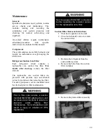
Page 38: ...ill not operate correctly and a service company is required only a company with service technicians qualified and experienced in both refrigerant chillers and air conditioning are permitted to service the systems to keep warranties in effect If assistance is required the service technician must contact AAON Replacement Parts Parts for AAON equipment may be obtained from your local AAON representat...

Page 39: ...It can also be installed to permit the separation and dispersal of air while fluid is actually circulating in the system Overview Body and cover are brass construction Air vent with silicone rubber seal Impurities do not usually affect function as maximum float line of water is always lower than the valve seal Float is high temperature resistant polyethylene Suitable for use with glycol systems Ca...

Page 40: ...proper separation of air from water The valve should be mounted only in a vertical position as its operation is based on the vertical movement of the float While the air vent valve is in operation back off the small vent cap two turns This is the proper operating setting which will allow air to be vented from the system It is advisable to leave the cap on to prevent impurities from entering the va...

Page 41: ... F Restricted Zone for normal touch or 80 C 176 F Unrestricted Zone for unintentional touch may be experienced steps should be taken to minimize contact or warn operators users that normal operating conditions will be exceeded In certain cases where the temperature of the pumped liquid exceeds the above stated temperature levels pump casing temperatures may exceed 100 C 212 F and not withstanding ...

Page 42: ...tor shaft and secure to the lifting device With the straps in place using a spacer bar if necessary to protect the motor fan cover the whole assembly can now be lifted securely Note Handling transportation and installation of this equipment should only be undertaken by trained personnel with proper use of lifting equipment Remove coupling guard and place lifting straps on each side of coupling use...

Page 43: ...ed or open slightly at start up to help eliminate trapped air When stopping the pump Close the discharge valve and de energize the motor DO NOT run the pump against a closed discharge valve for an extended period of time A few minutes maximum Star Delta motor starters should be fitted with electronic mechanical interlocks that have a timed period of no more than 40 milliseconds before switching fr...

Page 44: ...her major pump components Motor Follow the lubrication procedures recommended by the motor manufacturer Many small and medium sized motors are permanently lubricated and need no added lubrication Generally if there are grease fittings evident the motor needs periodic lubrication and if there are no grease fittings evident no periodic lubrication is required Check the lubrication instructions suppl...

Page 45: ...mental to the pump internals and sealing arrangement Proper operation cannot be guaranteed if the above conditions are not adhered to Note Particular care must be taken to check the following before the pump is put into operation 1 Pump primed 2 Rotation OK 3 Lubrication OK 4 Pipe work properly supported 5 Voltage supply OK 6 Overload protection OK 7 Is the system clean 8 Is the area around the pu...

Page 46: ...of One Side 1 Stop the pump to be serviced 2 Close and lock the suction and discharge valves as per instructions below 3 Ensure seal flush line interconnection valve is closed and drain the isolated casing 4 Service isolated pump as required Procedure for Starting the Pump after Servicing 1 Ensure serviced pump is fully re assembled including all seal flush lines and drain plugs 2 Fill the dry cas...

Page 47: ...m 4 4 Raise the locking handle 3 so that the cam on the base of the handle forces the pin of the locking arm 4 towards the pump to be isolated The locking handle 3 should be raised to between 45 degrees and the vertical position 5 Tighten set screw 11 to lock the locking handle 3 in position This handle should not be rotated past the vertical position Note Ensure the isolated pump is not operating...

Page 48: ...o be isolated The locking handle 3 should be raised to between 45 degrees and the vertical position This handle should not be rotated past the vertical position 5 Tighten set screw 11 to secure the locking handle 3 in position Unlocking 1 Open the interconnecting valve on the seal flush line to pressurize the serviced pump and vent air through bleeder valve on series 4302 Close these valves once t...

Page 49: ...49 ...

Page 50: ...50 ...

Page 51: ... mishandling should be reported immediately to the carrier and noted on the freight bill Operation No special attention need be paid to the Suction Guide at start up The fitting is stationary and will strain the pumped fluid and stabilize the flow into the pump automatically Temporary strainer must be removed following system clean up After all debris has been removed from the system or a maximum ...

Page 52: ...ange adapter on the valve body ensuring that the lugs on each half of the flange adapters are located between the anti rotation lugs on the valve body as shown Insert two bolts of specified size Table A1 to secure the halves of the flange adapter to the valve body as shown Table A1 Armgrip Flange Adapter Details Valve Size 125 psi 150 psi 250 psi 300 psi Ductile Iron Bolt Ductile Iron Bolt No Size...

Page 53: ...s should be tightened to 70 ft lbs torque minimum to assure firm metal to metal contact When raised face flanges are used there will be a gap between the faces of the outer diameter 6 Flange gaskets are not interchangeable with other mechanical pipe couplings or flange gaskets Recommended Bolt Tightening Procedure Field Conversion Straight to Angle Pattern Valve 1 Open valve at least one complete ...

Page 54: ... With valve in fully open position locate the pressure differential on left hand side of the Flo Trex Performance Curve with Valve in Full Open Position chart and extend line horizontally across to valve size being used Drop line vertically down and read flow rate from bottom of chart Safety glasses should be worn Probes should not be left inserted into fittings for long periods of time as leakage...

Page 55: ...ttled position Step 4 Locate percentage of valve opening on the bottom scale of Inherent Flow Characteristic Curve with Valve in Throttled Position Project line vertically up to intersect with the Valve Characteristic Curve and from this point project line horizontally across to the left of the chart and record the percentage of maximum flow rate Step 5 On the Flo Trex Performance Curve with Valve...

Page 56: ...valve setting Step 2 Turn the valve stem counterclockwise until the valve is fully open and will not turn any further Torque to a maximum of 45 ft lbs This will ensure good metal to metal contact and minimal leakage Step 3 The valve bonnet may now be removed There may be a slight leakage as the metal to metal backseating does not provide a drip tight seal Step 4 Clean exposed portion of valve stem...

Page 57: ...57 Pressure Temperature Limits Flo Trex Cross Section ...

Page 58: ...tor should verify the following items 1 Is there any visible shipping damage Yes No 2 Is the unit level Yes No 3 Are the unit clearances adequate for service and operation Yes No 4 Do all access doors open freely and are the handles operational Yes No 5 Have all shipping braces been removed Yes No 6 Have all electrical connections been tested for tightness Yes No 7 Does the electrical service corr...

Page 59: ...the water piping been insulated Yes No 7 Is the glycol the proper type and concentration N A if water Yes No 8 What is the freeze point of the glycol N A if water ______________________________ Chiller Configuration Air Cooled Chiller Low Ambient Control Condenser Safety Check No Water Leaks Water Flow ________ gpm Chilled Water In Temperature ________ F Chilled Water Out Temperature ________ F Co...

Page 60: ...iquid N A Refrigeration System 2 Cooling Mode Pressure Saturated Temperature Line Temperature Sub cooling Superheat Discharge N A N A Suction N A Liquid N A Condenser Fans Alignment Check Rotation Nameplate Amps________ Number hp L1 L2 L3 1 2 3 4 5 6 7 8 Pumping Package hp L1 L2 L3 Flow gpm Chiller Building Pump 1 Chiller Building Pump 2 ...

Page 61: ...ument any service repair or adjustments AAON Service and Warranty Departments are available to advise and provide phone help for proper operation and replacement parts The responsibility for proper start up maintenance and servicing of the equipment falls to the owner and qualified licensed technician Entry Date Action Taken Name Tel ...

Page 62: ......
Page 63: ...2017 Added picture to show the open base Added phase imbalance discussion Added frequency ranges for VFD compressors Changed the minimum compressor cycling times to 3 minutes Added suction line filter removal instructions May 2018 Updated technical support contact information June 2018 Updated E coated coil cleaning procedure Updated Flo Trex Combination Valve section Minor Revision changed to A b...

Page 64: ... available Parts For replacement parts please contact your local AAON Representative It is the intent of AAON to provide accurate and current product information However in the interest of product improvement AAON reserves the right to change pricing specifications and or design of its product without notice obligation or liability Copyright AAON all rights reserved throughout the world AAON and A...

Reviews: