8
IM 725 (1-02)
Caulk
(Top and 2 Sides)
Louvers
Drain Holes (Do Not Block)
Flange (4 Sides)
1" Minimum
Lintels (By Others)
Bird Screen
Sealed Cement
Mortar Pitched
Away from Unit
Toward Louver
Vertical or Horizontal Blade
Wall Intake Louver
(Flanged)
(Vertical Blade Shown)
Lintels (By Others)
Louvers
Drain Holes
(Do Not
Block With
Mortar or
Caulking
Materials
Bird Screen
Sealed Cement
Mortar Pitched
Away from Unit
Toward Louver
1" Minimum
Vertical or Horizontal Blade
Wall Intake Louver
(Recessed Without Flange)
(Horizontal Blade Shown)
Notes:
1.
Horizontal blade wall louver shown. Vertical blade wall louver also available
with Ventimatic shutter.
2.
Optional exterior grille matches unit ventilator wall louver in material and
design. Mounted on wall louvers.
3.
Optional steel interior wall grille should be used to conceal the interior wall
opening whenever the Ventimatic shutter is not located behind shelf cabinets
or DraftStop enclosure. Hardware to mount the interior wall grille is not
included.
Installing the VentiMatic Shutter Assembly
The VentiMatic Shutter Assembly is mounted on an installed wall
louver. For larger units with 100% ventilation air dampers, two
VentiMatic Shutters may be mounted side by side on the same louver.
See figure 20.
The size and appearance of the wall louvers with or without optional
grilles used with the unit ventilator, and the VentiMatic Shutter, are
identical.
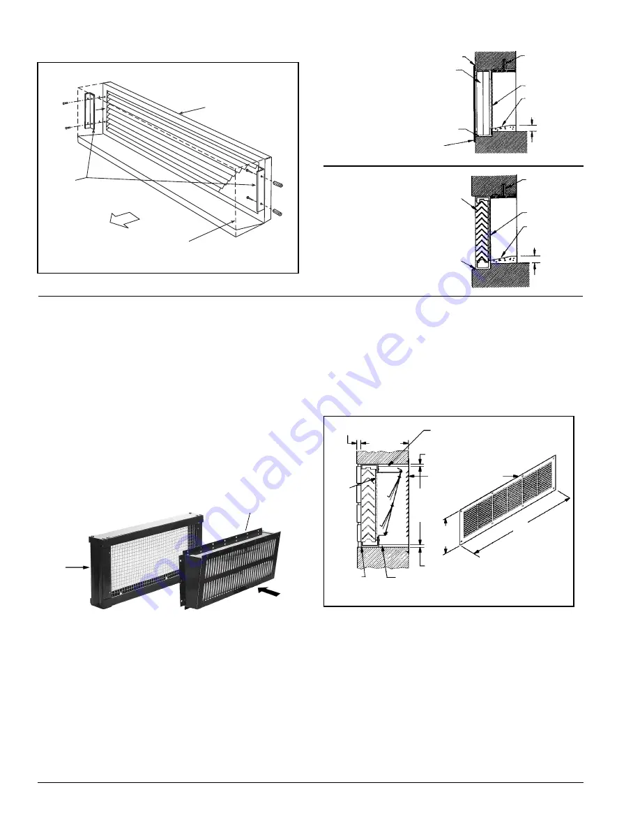
Figure 15 - Suggested method for fastening louver (without flange)
inside wall opening .
Figure 18 - Louver Details, Dimensions
As Directed
By Architect
3
⁄
4
" (19mm) Approx.
7"
(178mm)
Cement Mortar
Steel Interior Wall Grille
(Optional) See Note 3
12
5
⁄
8
"
(314mm)
3
⁄
4
" (19mm) Approx.
Bird
Screen
Do Not Block Drain
Holes With Caulk or
Mortar
Not
Less
Than 9"
(229mm)
Cement Mortar
C
(see table 1, page 7)
Wall Opening
Louver
(Bird Screen Not Shown)
Angle Iron
(by others)
Room Side
Exterior
Figure 16 - Louver Installation Views
Note: Birdscreen and louver are shipped in one (1) piece.
Pre-Installation Considerations
VentiMatic
™
Shutter Assembly
In many installations, an AAF
®
-HermanNelson
®
VentiMatic Shutter
Assembly is specified. See figure 17. This one-way shutter is a
continuously variable, gravity actuated, room exhaust vent that operates
in direct response to positive static pressure. It opposes any airflow
into the room and allows a slight positive pressure.
It is important that the VentiMatic shutter and unit ventilator louvers
are mounted on the same wall. This neutralizes the effect of the wind.
Forcing excess air into the room through the unit ventilator louver
overcomes the same wind pressure that works to keep the VentiMatic
shutter closed. This prevents room air exhausting from the room
through the VentiMatic shutter.
Figure 17 – VentiMatic Shutter Assembly
Outside
Louver
VentiMatic Shutter
Roomside
Relief Air
When installing VentiMatic Shutter(s) on the wall louver, make sure
all moving parts are free to operate unobstructed and placed level and
plumb for proper operation. If optional steel interior wall grille is
furnished, install as shown in Figure 18.


