background image

18

DMA8825 / DMA8813 / DMA8425 / DMA8413

English

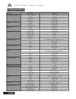
PARAMETERS

Function

Parameter

Range

Compressor / Limiter

Compressor Threshold

-50 dB to 0 dB

Ratio

1:1 to 20:1

Limiter Threshold

-50 dB to 0 dB

Output Gain

0 dB to 18 dB

Attack / Release

1 ms to 8 seconds

Gate

Threshold

-50 dB to 0 dB

Range

-90 dB to 0 dB

Attack / Hold / Release

1 ms to 8 seconds

Expander

Threshold

-50 dB to 0 dB

Ratio

1:1 to 20:1

Attack / Release

1 ms to 8 seconds

Delay

Delay Time (mS)

0�0 to 680�0 ms

Delay Time (meters)

0�0 to 245�5

Delay Time (feet)

0�0 to 805�4

Temperature (C)

0° to 50°

Temperature (F)

32° to 122°

4-band Equalizer

Type

BPF, Notch, Peak, HPF, LPF, High Shelf, Low Shelf

Gain

-18 dB to +18 dB

Frequency

20 Hz to 20 kHz

Q

0�1 to 10

31-band Graphic EQ

Frequencies

20 Hz to 20 kHz

Range

-12dB to +12dB

Q

1�6 to 10

Filters

Type

HPF (6 dB, 12 dB, 18dB, 24dB), LPF (6 dB, 12 dB, 18dB, 24dB),  

High Shelf, Low Shelf, Peak, APF, BPF, Notch

Gain

-18 dB to +18 dB

Frequency

20 Hz to 20 kHz

Q

0�1 to 10

Feedback Silencer

Threshold

-50 dB to 0 dB

Release Time

10 sec/dB to 300 sec/dB

Gain

-20 dB to 0 dB

Frequency

20 Hz to 20 kHz

Q

4�5 to 10

VCA

Gain

-∞ to 6 dB

Automatic Level Control

In Target

0 dB to -50 dB

Below Target

-30 dB to 0 dB

Ratio

1:5~20:1

Increase Gain

40ms/dB to 1000ms/dB

Decrease Gain

1000ms/dB to 40ms/dB

Hold Time

0s to 10s

Ducker

Source

Analog 1 to 8, Network 1 to 8, AES/EBU

Threshold

-50 dB to 0 dB

Depth

-80 dB to 0 dB

Attack / Release 

0�2s to 20s

Crossover

HPF / LPF Type

Butterworth 12dB, 18dB, 24dB

HPF / LPF Frequency

20 Hz to 20 kHz

Signal Generator

Sine Wave Frequencies

20Hz to 20KHz

Sweep Wave Start/End Frequencies

20Hz / 20KHz

Sweep Wave Hold Time

50ms to 2000ms

Signal Level Range

-60dB to -10dB

Summary of Contents for DMA8413

Page 1: ...User s Manual Manual del Usuario Digital Matrix Amplifiers DMA8825 DMA88 1 3 DMA8425 DMA84 1 3 ...

Page 2: ... 4 INSTALLATION AND SETUP 5 RACK MOUNTING 5 CONNECTION 5 DIGITAL I O EXPANSION CARD 6 STAND ALONE CONTROL 7 REMOTE CONTROL 7 CONTROL SOFTWARE 10 SPECIFICATIONS 17 PARAMETERS 18 Asystems reserves the right to alter any information contained within this manual without prior notice V1 3 06 20 2016 TABLE OF CONTENTS ...

Page 3: ...ghting storms or when unused for long periods of time 14 Refer all servicing to service personnel Servicing is required when the apparatus has been damaged in any way such as power supply cord or plug is damaged liquid has been spilled or objects have fallen into the apparatus the apparatus has been exposed to rain or moisture does not operate normally or has been dropped IMPORTANT SAFETY INSTRUCT...

Page 4: ...URES 8 input channels available via 3 pin Euroblock connections and stereo RCA inputs Full control possible through onboard software accessed with VGA display and USB mouse connected Built in multi channel amplifier for low impedance or line distribution application For power output levels for individual models please consult the Specifications on page 17 40 bit floating point processor with inter...

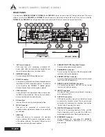
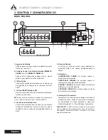
Page 5: ...is drawn in here Please do not cover these vents for any reason as you risk overheating the DMA 6 Reset Button A pinhole button is included for resetting the DMA series matrix amplifier to the factory default settings 7 Indicators POWER Lights when the device is on DISABLE Lights when the power switch is disabled STANDBY UNLOCK Lights when DMA device is in the Standby mode PROTECT Lights when the ...

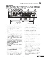
Page 6: ...cting passive loudspeakers 9 PERIPHERAL Connector For connecting the Asystems RM 6E programmable remote control sold separately 10 PRESET RECALL Connector For connecting Asystems RM 4 series remote preset recall control sold separately 11 REMOTE LEVEL CONTROL Connector For connecting Asystems RM 2VR series remote level control sold separately 12 INPUT Connectors Two types of input connectors are o...

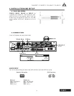
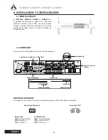
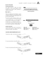
Page 7: ...rack space 4 2 CONNECTIONS Connect all necessary input and output devices AUDIO INPUT Input can be achieved through correctly wiring the Euroblock connectors and RCA connectors 4 INSTALLATION AND SETUP 4 1 RACK MOUNTING To Monitor Display USB Mouse Audio In To PC Internet Intranet DMA8425 DMA8413 AUX Out AUX Out Amplified Out Amplified Out Euroblock Connectors RCA Connectors Balanced PIN 1 Shield ...

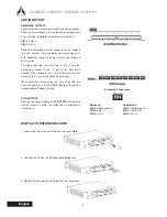
Page 8: ...o the pin of the next even channel When bridged the pin of the even channel becomes the pin of the bridged new output When activating bridge mode be sure to go into the Control Panel menu of the DMA software and click the corresponding Bridged button AUX OUTPUTS Offering line level signals AUX OUTPUT connectors can be wired as either as balanced or unbalanced connections DIGITAL I O EXPANSION CARD...

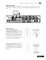
Page 9: ...EL CONTROL connectors of the DMA matrix amplifier The channels controlled by the VR is determined by the wiring of the control Please note the ground for channel 2 is internally wired to channel 1 Only one grounding pin needs to be connected to the DMA In the example found to the right channels one and two can be remotely controlled using the RM 2VR 2 RM 4 REMOTE PRESET RECALL CONTROL With Asystem...

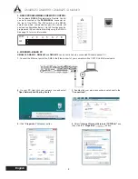
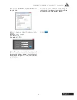
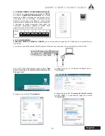
Page 10: ...motely using the RM 6E See page 16 for more information 4 WINDOWS BASED PC DMA8825 DMA8813 DMA8425 and DMA8413 can be controlled via a connected Windows based PC 1 Connect the Ethernet port of the DMA to the Ethernet port of your computer with a CAT5 RJ 45 Ethernet cable 2 On your PC right click your network icon and select Open Network and Sharing Center 4 Click Properties button 3 Double click y...

Page 11: ...Password ASYSTEMS Hint In the event you are unable to log in using any of the main user accounts connect a monitor and mouse to the DMA digital matrix amplifier This will allow you to view network settings while in stand alone mode and reset all accounts 7 Launch the control software by double clicking the executable file The latest version of the DMA software can always be found on the Asystems w...

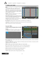
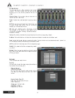
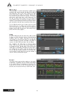
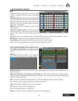
Page 12: ... to the Control Panel tab Clear Clicking this button resets all DSP configurations Channel In Matrix In this page you can assign any input source to any input channel by clicking the corresponding cell in the cell matrix Example The image below shows how to assign input source 1 and 2 to Channel In 1 and Input source 2 to Channel In 2 Meter Pre Meter Post This buttons sets all input sources to pre...

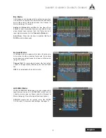
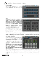
Page 13: ... ALC and DUCK work simultaneously Network Matrix In this page you can assign which kind of input source to be output via the connected Dante card All controls are as same as controls under the Channel In Matrix tab page 10 except Channel Out To view output channel the last output control in the signal path effected by the Control Panel tab LIM To enable disable the built in Limiter AES EBU Matrix ...

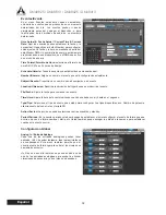
Page 14: ...g channel Pre Post This button allows you to adjust the output meter between a pre fader and post fader meter Duck Activate the ducking feature by pushing this button The duck function can be activated as ducker 1 ducker 2 or off the settings of which are decided by their respective menus INV This button will invert the phase of the corresponding signal ON OFF This button will turn the correspondi...

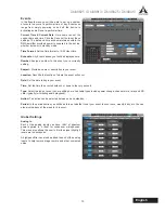
Page 15: ... description to your event Location Describe the location of where the event will occur Date Set the date to begin your event Time Set the time the event should occur down to the very second Type Select the type of event you are setting here Available types include power change channel mute relay and SD card typically for initiating audio playback Action The action can be selected between on and s...

Page 16: ... time control will determine the time the duck feature will remain active as the source signal drops back below the set threshold ALC Auto Level Control An autoleveler will allow users to dynamically change the level of an input or output signal to match a predefined level set by the user The autolevel function can be activated for each individual mix in the matrix pages The settings for these aut...

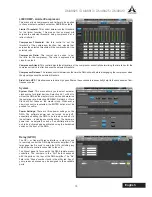
Page 17: ... to essentially help rid these channels of low frequency noise System System Clock This menu allows you to select a master clock source for digital devices Selecting 44 1 or 48 kHz will set the DMA as the master clock source and determine the sampling rate Selecting AES EBU Network or Word Clock will set these as the master clock Whenever a new clock source is selected the ENTER button must be pus...

Page 18: ...age 8 Utility All of the DSP processes can have their settings saved for later use While there are a number of factory presets available users are always encouraged to find their own settings and save them for later use The DMA has onboard storage for a number of settings to be saved or users can connect USB flash drives to save settings Also available in the Utility menu is a firmware update butt...

Page 19: ...0 5 0 5 0 5 0 5 Distortion THD N typical 8 ohm load 10dB below rated power 20Hz 20kHz 0 5 0 5 0 5 0 5 Frequency Response 20Hz 20kHz 1dB 20Hz 20kHz 1dB 20Hz 20kHz 1dB 20Hz 20kHz 1dB Damping Factor 8 ohm load 1kHz 250 250 250 250 Input Impedance 20K Ohm balanced 20K Ohm balanced 20K Ohm balanced 20K Ohm balanced Maximum Input Level 24dB 24dB 24dB 24dB Cooling Temperature dependent speed controlled a...

Page 20: ...20 Hz to 20 kHz Range 12dB to 12dB Q 1 6 to 10 Filters Type HPF 6 dB 12 dB 18dB 24dB LPF 6 dB 12 dB 18dB 24dB High Shelf Low Shelf Peak APF BPF Notch Gain 18 dB to 18 dB Frequency 20 Hz to 20 kHz Q 0 1 to 10 Feedback Silencer Threshold 50 dB to 0 dB Release Time 10 sec dB to 300 sec dB Gain 20 dB to 0 dB Frequency 20 Hz to 20 kHz Q 4 5 to 10 VCA Gain to 6 dB Automatic Level Control In Target 0 dB ...

Page 21: ... PANEL TRASERO 23 INSTALACIÓN Y CONFIGURACIÓN 24 MONTAJE RACK 24 CONEXIÓN 24 TARJETA DE EXPANSIÓN DIGITAL I O 25 CONTROL AUXILIARES 26 CONTROL REMOTO 26 SOFTWARE DE CONTROL 29 ESPECIFICACIONES 36 PARAMETROS 37 Asystems se reserva el derecho de modificar cualquier información contenida en este manual sin previo aviso ÍNDICE ...

Page 22: ......

Page 23: ...el DSP 2 CARACTERÍSTICAS 8 canales de entrada disponibles a través de conexiones y entradas euroblock RCA estéreo de 3 pines Los conectores VGA y USB permiten su uso como un sistema autónomo Amplificador multicanal puede funcionar con distribución de baja impedancia o aplicación de distribución linear El procesador de punto flotante de 40 bits con muestreo interno es seleccionable entre 44 1 y 48 ...

Page 24: ...orre el riesgo de sobrecalentamiento de la DMA 6 Botón de Reinicio Se incluye un botón de reinicio para restablecer el dispositivo DMA a los valores predeterminados de fábrica 7 Indicadores ALIMENTACIÓN POWER Se ilumina cuando el dispositivo esté encendido DESACTIVAR DISABLE Se enciende cuando el interruptor de encendido está desactivado STANDBY UNLOCK Se ilumina cuando el dispositivo DMA está en ...

Page 25: ... SALIDAS DE ALTAVOZES salida amplificada Para conectar con altavoces pasivos 9 Conector PERIFÉRICO Peripheral Para conectar con el control remoto programable de Asystems RM6E se vende por separado 10 Conector de PREESTABLECIDO DE RECUPERACIÓN PRESET RECALL Para conectar con control remoto serie RM 4 de Asystems se vende por separado 11 CONTROL DE NIVEL REMOTO REMOTE LEVEL CONTROL Para la conexión ...

Page 26: ... los dispositivos de entrada y salida necesarios ENTRADA DE AUDIO La Entrada se puede lograr a través de conectores Euroblock y RCA correctamente cableados 4 INSTALACIÓN Y CONFIGURACIÓN 4 1 MONTAJE RACK Visualización del Monitor Ratón USB Entrada Audio Para PC Internet Intranet DMA8425 DMA8413 Salida AUX Salida AUX Salida Amplificada Salida Amplificada Conectores Euroblock Conectores RCA Balancead...

Page 27: ...puenteado el pin del canal par se convierte en el pin de la nueva salida combinada Al activar el modo de puente Bridge asegúrese de entrar en el menú Panel de control del software de DMA y haga clic en el botón correspondiente puenteado Bridged SALIDAS AUXILIARES Ofreciendo señales de nivel línear los conectores de salida AUX AUX OUTPUT se pueden conectar como conexiones equilibradas o desequilibr...

Page 28: ...dor Matrix Los canales que son controlados por el VR se determinan por el cableado Tenga en cuenta que la conexión a tierra para el canal 2 está conectado internamente al canal 1 Sólo una clavija a tierra tiene que ser conectada a la DMA En el ejemplo que figura a la derecha los canales 1 y 2 se pueden controlar de forma remota mediante la RM 2VR 2 CONTROLADOR REMOTO DE AJUSTES PRE ESTABLECIDOS RM...

Page 29: ... utilizando el RM 6E Mirar pagina 35 para una información más amplia 4 PC CON WINDOWS El DMA8825 DMA8813 DMA8425 y DMA8413 puede ser controlado a través de un PC Windows con un cable Ethernet CAT5 RJ45 1 Conecte el puerto Ethernet de la DMA al puerto Ethernet de su ordenador con un cable Ethernet RJ 45 CAT5 2 En el PC haga click derecho sobre el icono Red Abierta y Recursos Compartidos Open Networ...

Page 30: ...0 200 Nombre de Usuario USER_1 Contraseña ASYSTEMS Sugerencia En el caso de que usted no pueda iniciar la sesión con cualquiera de las principales cuentas de usuario conectar un monitor y ratón en el DMA Esto le permitirá ver los ajustes de red podra restablecer todas las cuentas mientras que se encuentra en modo autónomo 7 Inicie el software de control haciendo doble clic en el archivo ejecutable...

Page 31: ...ol Clear Al hacer clic en esta tecla para que se aplique todas las configuraciones DSP Channel In Matrix Matrix de Canal de Entrada En esta página se puede asignar una fuente de entrada en el canal elegido haciendo clic en una celda de la matriz celular Ejemplo Para asignar la fuente de entrada 1 y 2 al entrada de canal 1 y la fuente de entrada 2 al entrada de canal 2 MEDIDOR PRE POST Puede utiliz...

Page 32: ...d puede asignar el tipo de fuente de entrada que quiere convertir en fuente de salida con la tarjeta de Dante que haya conectado Todos los controles son los mismos que en la ficha Channel In Matrix excepto Channel Out Canal de Salida Podrá utilizar esta opción para ver los canales de salida el último control de salida en la ruta de la señal afectados por la ficha Panel de control LIM Para activar ...

Page 33: ...terno para el canal correspondiente Pre post Este botón permite ajustar el medidor de salida entre un medidor pre fader y post fader Duck Permite activar la función Ducking pulsando este botón La función Duck se puede activar como ducker 1 ducker 2 o apagado la configuración de los cuales se decidió por sus respectivos menús INV Este botón invierte la fase de la señal correspondiente ON OF Este bo...

Page 34: ...ipción a su evento Location Ubicación Describa la ubicación del lugar donde se producirá el evento File Fecha Ajuste la fecha para comenzar su evento Time Hora Ajuste la hora del evento indicando cuando ese debe ocurrir hasta en el segundo Type Tipo Seleccione el tipo de evento que usted quiere configurar Los tipos disponibles son Cambio de potencia silenciamiento del canal relay y tarjeta SD Acti...

Page 35: ...or debajo del umbral pre establecido ALC Auto Level Control Este auto regulador permitirá a los usuarios cambiar dinámicamente el nivel de una señal de entrada o salida para que esa coincida con un nivel predefinido e establecido por el usuario La función auto nivelante se puede activar para cada mezcla individual en las páginas de la matriz Los ajustes para estos auto niveladores se pueden encont...

Page 36: ...nú le permite seleccionar una fuente de reloj maestro para la sincronización de los dispositivos digitales Seleccionando 44 1 o 48 kHz fijará la DMA como fuente de reloj maestra y determinara la frecuencia de muestreo Selección de AES EBU Network o Word Clock fijará estos como el reloj maestro Cada vez que se selecciona una nueva fuente de reloj se pulsa el botón ENTER para confirmar Power Setting...

Page 37: ...a 27 Utility Todos los procesos DSP pueden tener sus ajustes guardados para su uso posterior Si bien hay una serie de presets disponibles los usuarios siempre se les animan a encontrar sus propias configuraciones y guardarlas para su uso posterior La DMA tiene a bordo un número de configuración a guardar los usuarios pueden conectar unidades flash USB para guardar las configuraciones También dispo...

Page 38: ...HD N típico carga de 8 ohmios potencia de 10 dB inferior al valor teórico 20Hz 20kHz 0 5 0 5 0 5 0 5 Respuesta de frecuencia 20Hz 20kHz 1dB 20Hz 20kHz 1dB 20Hz 20kHz 1dB 20Hz 20kHz 1dB Factor de Amortiguamiento Dumping carga de 8 ohmios 1 kHz 250 250 250 250 Impedancia de entrada 20K Ohm simetrico 20K Ohm simetrico 20K Ohm simetrico 20K Ohm simetrico Nivel máximo de entrada 24dB 24dB 24dB 24dB Enf...

Page 39: ...0 0 ms Delay Time meters Tiempo de retardo metros 0 245 5 Delay Time feet Tiempo de retardo pies 0 805 4 Temperature C Temperatura C 0 a 50 Temperature F Temperatura F 32 a 122 4 band Equalizer Ecualizador de 4 bandas Type Tipo BPF Notch Peak HPF LPF High Shelf Low Shelf Gain Ganancia 18 DB a 18 dB Frequency Frecuencia 20 Hz a 20 kHz Q Q 0 1 a 10 31 band Graphic EQ Ecualizador graphico de 31 banda...

Page 40: ...ación de señal Source Fuente Analógica 1 a 8 Red 1 a 8 AES EBU Threshold Umbral 50 DB a 0 dB Depth Profundidad 80 DB a 0 dB Attack Release Ataque Liberación 0 2s a 20s Crossover HPF LPF Type Tipo HPF LPF Butterworth 12 dB 18 dB 24 dB HPF LPF Frequency Frecuencia HPF LPF 20 Hz a 20 kHz Signal Generator Generador de señales Sine Wave Frequencies Las frecuencias de onda sinusoidal 20Hz a 20KHz Sweep ...

Page 41: ......

Page 42: ...www asystems sys com ...

Reviews: