20
A44-P
8. SPARE PARTS
8.1 SPARE PARTS LIST
Even though the machine has been submitted to several tests and functional checks, we listed below the components that
we suggest you to have a minimum and sufficient set of. This will help guarantee the shortest possible downtime.
TABLE 8.1 - A
COMPONENT
• WEDGES DRIVER BLADE
• WEDGES CLAW-HEADS
• “L” SHAPED SUPPORT (WEDGES GUIDE)
• VALVES-REDUCERS-REGULATORS
• VERTICAL AND HORIZONTAL CLAMPING
• GASKETS
8.2 SPARE PARTS ORDERING
We remind you that only a qualified technician can repair the machine.
Therefore we suggest the intervention of your local distributor or A-Plus Automation Center of Technical Assistance, which
has access to qualified staff, proper equipment and tools, and who uses original spare parts.
To order the above spare parts, send the following data by fax, e-mail or letter:
• Model of the Machine
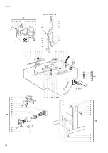
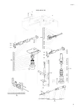
• Code of drawing scheme
• Reference number of spare part or group indicated on the mechanical drawing
• Code number of single or group spare part
9. MACHINE DEMOLITION
9.1 MACHINE DEMOLITION
When scrapping the machine, group components by chemical composition and dispose of separately in accordance with
applicable legislation. Do not dispose of non-biodegradable materials, lubricant oils and non-ferrous articles (rubber, PVC,
plastics etc.) in the environment.
10. ATTACHMENTS
10.1 DECLARATIONS
You can find here attached the following declarations
• Declaration of conformity to the Norm 89/392/CEE
10.2 SCHEMATICS
You can find here attached the following schemes:
• (A) Mechanical Schematic
• (B) Pneumatic Schematic
• (C) Plate locations
• (D) Sharpening Table
Summary of Contents for A44-P
Page 3: ...3 A44 P...
Page 21: ...21 A44 P...
Page 24: ...24 A44 P DWG A44 P 01...
Page 25: ...25 A44 P DWG A44 P 02...
Page 26: ...26 A44 P SCHEMES B Pneumatic Scheme...
Page 27: ...27 A44 P...
Page 28: ...28 A44 P SCHEME C Plates location...
Page 30: ...30 A44 P...
Page 31: ...31 A44 P...
Page 32: ......


