10
A44-P
4.2 WAREHOUSING AND STORAGE PROCEDURES
• In order to avoid that the components cause dangers or are damaged, the storage area must be covered (preferably a
closed area) and accessible only for authorised personnel.
• Avoid corrosive materials that could touch the machine
• Lubricate the parts which are not painted or chromed.
4.3 UNPACKING
According to the installation requirements, the personnel authorised by the manufacturer will unpack the components in the
most suitable way and will check their integrity. Keep all packages (carton box, pallets, etc.) for future use and dispose of the
protection materials (nylon, polystyrene, etc.) according to the laws in force.
4.4 PRELIMINARY ARRANGEMENTS
In order to install the machine it is necessary to prepare a working area (a table) adequate to the machines dimensions and
the length of moulding you will be working with. To fulfill the characteristics of precision and steadiness, the bench frame
assembling machines must be positioned on a solid and leveled plane able to sustain the weight of the machine. The bench
must be studied and prepared by the customer and/or qualified staff.
4.5 PNEUMATIC CONNECTION
The machine is controlled by a foot pedal that allows the activation of frontal clamp and by a joystick that controls the vertical
clamping snd wedge insertion.
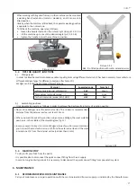
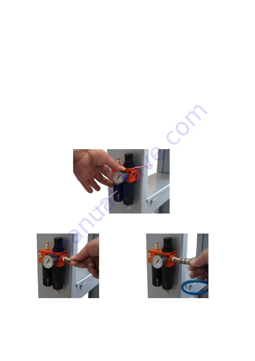
Screw the supplied manometer in the air filter lubricator placed on the floor stand right side (see pict. 4.6.1.1).
Picture 4.6.1.1
Use the supplied fast clutch fitting to connect the air compressed system. You could use also another fitting suitable with
your pneumatic system (see pict. 4.6.1.2 and 4.6.1.3).
Picture 4.6.1.2
Picture 4.6.1.3
Once connected the machine with the pneumatic system, check the functioning of the 2 positions foot pedal and that of the
Wedges firing lever (2 positions control lever).
The proper functioning of the foot pedal is the following:
• when the foot pedal is PRESSED HALF WAY it activates the horizontal clamp
A
B
Summary of Contents for A44-P
Page 3: ...3 A44 P...
Page 21: ...21 A44 P...
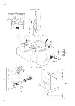
Page 24: ...24 A44 P DWG A44 P 01...
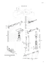
Page 25: ...25 A44 P DWG A44 P 02...
Page 26: ...26 A44 P SCHEMES B Pneumatic Scheme...
Page 27: ...27 A44 P...
Page 28: ...28 A44 P SCHEME C Plates location...
Page 30: ...30 A44 P...
Page 31: ...31 A44 P...
Page 32: ......


