


Residen al Gas Tankless Water Heater Use and Care Guide • 41
INSTALLATION
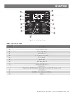
7
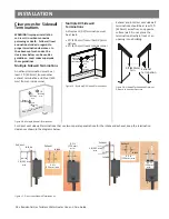
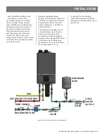
Make the electrical
connec on to the water
heater. Follow all local codes
or in the absence of local codes, with
the Na onal Electrical Codes: ANSI/
NFPA 70 in the USA.
8
Verify all electrical
connections are secure.
9
Replace the front cover and
turn on power to the water
heater.
10
Follow the instructions in the
Getting Started section of
this manual.
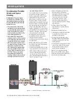
Cascade System
The Cascade System allows up to 12
heaters of the same input to be linked
in a Parent/Child con
fi
gura on. Do not
link heaters of di
ff
erent input rates
together.
WARNING! Working on an energized
circuit can result in severe injury or
death from electrical shock.
1
The Cascade system should
be configured with the
Parent water heater as the
first water heater connected to the
cold water supply and the Child units
will follow sequentially. See Figure 39.
2
Before proceeding disconnect
electrical power to all water
heaters in the Cascade
configuration.
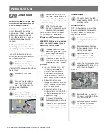
3
Remove the front cover(s)
and keep the two screws
from both the Parent and
Child water heaters for re-installation.
4
On the Parent water heater
lift the plastic clip locking the
control panel in place and
lower it down out of the way.
5
Remove and keep the clear
plastic covers over the
Printed Circuit Board (PCB).
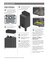
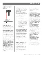
6
On the bo om of the water
heater locate the rubber
access grommet. Route the
single harness end of the Cascade
Linking Cable through the bo om and
around to the circuit board.
NOTICE: The cable should be routed
under the circuit board assembly to
prevent strain to the wiring harness.
Rubber Grommet
Figure 38 -
Bo om of water heater - Grommet.
7
Use Figure 39 as a reference
to locate the connection
point for the Parent Cascade
Unit. Use the single harness end of
the Cascade Linking Cable to make
the initial connection.
8
Follow steps 4-6 to route the
double harness end of the
Cascade Linking Cable to the
printed circuit board on the first Child
water heater.
9
If more than one Child water
heater is used then route the
single harness end of the
second Cascade Linking Cable through
rubber grommet on the bo om of the
fi
rst Child water heater and connect it
to the open harness on the
fi
rst
Cascade Linking Cable as shown in
Figure 39.
10
Once all connections are
made, the water heaters
must be assigned their
position in the system. Turn on the
power supply to all of the water
heaters, making sure there is no
water flow.
11
On the Parent water heater
simultaneously press and
hold the SETTING and UP
buttons until C00 appears.
12
Press the UP arrow button to
reach the C13 option, then
press SETTING button to enter that
option.
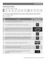
NOTE: C13 defines the number of
Child water heaters that will be
connected to the parent unit.
Enter the number of Child water
heaters attached to the parent water
heater and press Settings to load the
number to memory. For example, if
the system consists of four total water
heaters, then enter 3 for three child
heaters into C13. Press the SETTING
button again to return to normal
operation.
13
After the Parent water heater
is configured, the Child water
heaters must be configured.
Perform the following steps on each
Child water heater.
14
Press and hold both the
SETTING and UP buttons until
C00 appears.
15
Press the UP arrow button to
reach the C14 option, then
press the SETTING button to
enter that option.
NOTICE: C14 defines the number
assigned to each Child water heater
connected to the parent water heater.
16
Enter number 2 for the first
Child water heater and press
the SETTING button to load
the number to memory. Repeat this
step assigning a sequencial number at
each additional Child water heater.
17
Press and hold the SETTING
button again to return to
normal operation.
NOTICE: A maximum 11 Child water
heaters can be connected to a
Cascade System of 12 total water
heaters.
18
Verify all electrical
connections and conduit
connections are secure.
19
Follow the instructions in the
Getting Started section of
this manual.


