Residen al Gas Tankless Water Heater Use and Care Guide • 17
Installa on Environment
Proper moun ng and clearance
The water heater shall be securely
mounted on a wall that can support
the weight of the water heater. A wall
moun ng bracket is supplied with the
water heater to securely mount the
water heater to wall studs. The water
lines, gas line, condensate drain line,
and pressure relief valve discharge
line shall be supported using
fi
eld
supplied pipe hangers. The water
heater shall not bear the weight of
these lines. The water heater requires
proper installa on clearance for
opera on and service as described in
Unit Clearances sec on.
Warning! The installer (licensed
professional) is responsible for the
correct installa on of the water
heater and for compliance with all
na onal, state/provincial, and local
codes.
Atmosphere temperature
Install the water heater in a
heated area where below freezing
temperatures cannot occur. A pipe
cover is recommended when the
water heater is installed outdoors
because it provides be er protec on
from the elements. The warranty will
not be covered if the water heater is
damaged due to freezing. See ”Freeze
Protec on System” on page 54.
Combus on air supply
The water heater requires fresh
combus on air and should be
free of corrosive elements and
fl
ammable vapors. If it is installed in
a contaminated area or in a con
fi
ned
area, direct ven ng installa on is
recommended.
Proper ven la on
For proper opera on the water heater
must be vented in accordance with
the sec on “Ven ng” of the current
edi on of the ANSI Z223.1/NFPA 54,
Na onal Fuel Gas Code in the United
States and/or Sec on 8 of the B149.1,
Natural gas and propane installa on
code in Canada, as well as applicable
local building codes.
Condensate Drain line
The condensate produced is acidic.
Drain the condensate in accordance
with all local codes and common
safety prac ces.
Unit Clearances
Warning! Maintain all clearances
around the water heater. Failure
to do so could create a
fi
re hazard,
poten ally leading to death, serious
injury, and/or property damage.
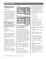
Indoor
Top:
12 in (305 mm)
Side:
3 in (76 mm)
Front:
4 in (102 mm)
Bottom:
18 in (458 mm)
Back:
0.5 in (13 mm)
Side:
3 in (76 mm)
Figure 4 -
Indoor Clearances
Top:
12 in (305 mm)
Side:
3 in (76 mm)
Front:
4 in (102 mm)
Bottom:
18 in (458 mm)
Back:
0.5 in (13 mm)
Side:
3 in (76 mm)
Overhang:
36 in (914 mm)
Figure 5 -
Outdoor Clearances
It is recommended that the front
should have 24 inches (610 mm) of
clearance for maintenance.
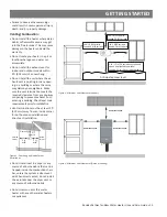
Moun ng the Water
Heater
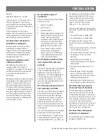
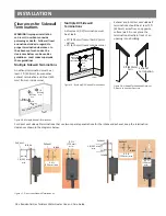
1. Secure the wall moun ng bracket
with the four supplied lag bolts to
the wall studs. See Figure 6. DO
NOT secure to the drywall only.
NOTICE: The supplied fasteners
are for wood studs only. When
moun ng on any other surface
use fasteners approved for that
wall material/construc on. Make
sure to level the bracket.
16” (406.4 mm) Center
New Construction Configuration Shown:
Drywall cut away to show horizontal bracing.
Wall Stud
Wall Stud
Horizontal Blocking - Top
Horizontal Blocking - Bottom
Screws
Figure 6 -
Wall bracket installa on.
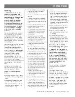
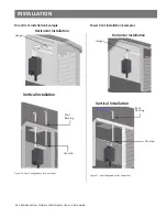
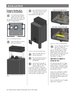
1. Hang the water heater on the wall
bracket. See Figure 7.
Wall
Bracket
Figure 7 -
Moun ng the water heater.
2. Secure the water heater
fi
rmly
fastening appropriate screws
into the upper bracket/bo om
brackets of the water heater and
wall. NOTICE: these screws are
not provided.
Secure with screws.
Secure with screws.
Figure 8 -
Use moun ng screws.
INSTALLATION

