NEED HELP? GIVE US A CALL
833.232.9711
NEED HELP? GIVE US A CALL
833.232.9711
INSTALLATION GUIDE
6
7
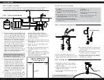
STEP 8 - Connect the system
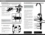
STEP 9 - Install the filter cartridges
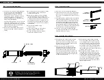
STEP 7 - Install the RO Membrane
1
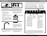
Remove the cover from the System Manifold.
2
Find the electrical connector for the system display
and connect it to the control board located inside
the cover. Use the diagram to determine the correct
connector.
3
The system includes a leak detector that will sound an
alarm if a leak is detected. Remove the leak detector
from its box and unwind the attached cable. Feed the
leak detector cable through the hole in the bottom
left corner of the System Manifold and connect it to
the mating plug found on the System Manifold. Place
the leak detector on the base of the cabinet under the
system with the A. O. Smith lettering facing up.
4
Place the cover on the System Manifold and
re-assemble the Manifold to the mounting screws
inside the cabinet as necessary.
1
Assemble two (2) O-rings to each of the three
(3) filter housings. One O-ring fits into the
groove at the top of the housings, and one fits
into the groove on the outside of the housings
above the mounting threads.
2
Remove all the filter cartridges and any
packaging materials from the filter housings.
Unwrap the #1 prefilter cartridge. Place it in
the #1 prefilter housing. Keep it centered in
the housing and assemble the housing into the
filter cap at the far right position. Twist it to the
right by hand and use the large housing wrench
to tighten it about 1/4 turn.
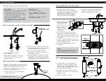
1
Remove the cover from the System Manifold,
if necessary, and locate the RO Membrane
housing. Ensure you do not damage the
Membrane when you remove it from its
packaging. Note the RO Membrane package
contains a small amount of preservative
solution designed to protect the Membrane
during storage and shipping.
It is also packaged with two clear covers on the
ends of the membrane. These covers are only
included to protect the Membrane seals during
shipping and they should be removed and
disposed of before installation.
2
Disconnect the white tubing from the inlet
quick-connect fitting on the RO Membrane
housing.
3
Unscrew the cap from the housing. The smaller
wrench included with the system may be
needed to loosen the cap.
4
Remove the Membrane from its sealed bag.
Insert the Membrane into the housing. Note
that one end of the Membrane has two pairs of
O-ring seals and the other has one pair. Insert
the end with two pairs of O-ring seals into the
housing first. Push the housing in gently until
it seats. Do not use excessive force to assemble
the Membrane.
5
Ensure the RO housing O-ring is
seated correctly.
6
Screw on the housing cap. Use the small
wrench to tighten it about 1/4 turn.
7
Reconnect the white tubing to the inlet
quick-connect fitting on the cap.
3
Unwrap the #2 Carbon Prefilter Cartridge.
Place it in the #2 prefilter housing. The end
of the Cartridge with the O-ring seals should
face up in the housing. Assemble the housing
to the center position in the RO unit. Ensure
you align the center of the Cartridge with the
center of the socket. Twist the housing to the
right by hand and use the large housing wrench
to tighten it about 1/4 turn.
4
Unwrap the #4 Claryum
®
Cartridge. Place it
in the #4 postfilter housing. The end of the
Cartridge with the O-ring seals should face up
in the housing. Assemble the housing to the
center position in the RO unit. Ensure you align
the center of the Cartridge with the center
of the socket. Twist the housing to the right
by hand and use the large housing wrench to
tighten it about 1/4 turn.
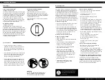
WARNING:
We recommend using an approved or certified professional.
Proper installation is the responsibility of the installer. Product failure due
to improper installation is not covered under the warranty.
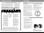
NOT USED
CONNECT TO
SYSTEM DISPLAY
CONNECT TO
LEAK DETECTOR
RO HOUSING
RO HOUSING O-RING
RO MEMBRANE
(note orientation)
RO COVER


