NEED HELP? GIVE US A CALL
833.232.9711
NEED HELP? GIVE US A CALL
833.232.9711
INSTALLATION GUIDE
2
3
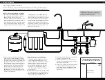
Prepare site and plan for installation
Prior to installation, read the entire manual to familiarize yourself with the system, and determine
the best location for installation. Ensure you check and comply with all local plumbing codes.
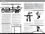
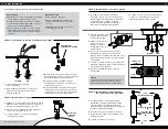
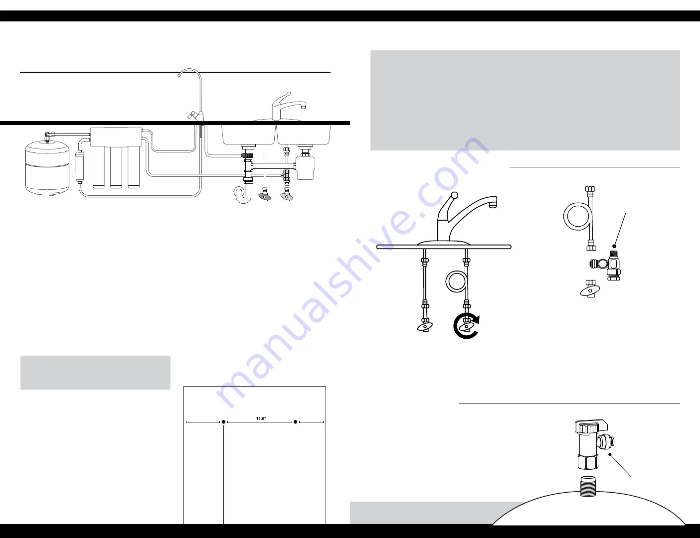
STEP 2 - Connect the feed water valve
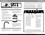
STEP 3 - Install the tank
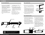
TO CONNECT:
1
This system comes with installation tubing. To
assemble the tubing, measure the required length
and cut.
2
With a utility knife, create a clean, square edge for
each tubing. Measure 3/4" from the end and mark
with a permanent marker.
3
Remove the lock clip and insert the tubing into
the lock sleeve, until the mark almost disappears.
Re-install lock clip.
TO DISCONNECT:
1
Remove the lock clip.
2
Gently push the lock sleeve down against
the fitting body.
3
Keep the lock sleeve pushed down and
pull on the tubing to remove.
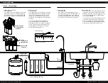
This system features quick-connect fittings.
STEP 1 - Position the system and tank
1
Turn off the cold water supply to the sink.
2
Turn on the kitchen cold water faucet to release
pressure and allow water to drain from the line.
1
Apply plumber’s tape 4 or 5 times clockwise
around the nipple on top of tank in the same
direction as threads.
2
Screw the tank shut-off valve onto the threads
by hand. Do not over-tighten.
3
Place the tank on its stand and position it in the
desired location.
3
Disconnect the faucet connector pipe from the
cold water supply. Place a towel underneath to
catch any drips.
4
Configure the feed water valve to match the
connection on the cold water supply.
5
Attach the feed water valve to the cold water
supply. Reconnect the faucet connector pipe to
the feed water supply valve.
Note: Do not over-tighten.
WATER FEED ADAPTER
TANK SHUT-OFF
VALVE
DRILL TWO 1/8" DIAMETER HOLES AND
ASSEMBLE TWO #10 MOUNTING SCREWS
TO HANG THE SYSTEM MANIFOLD
4.0"
MINIMUM
3.0"
MINIMUM
18.0" MINIMUM
FROM FLOOR
TIP
Temporarily place System Manifold, Remineralizer,
and Tank into the under sink cabinet or desired location to
ensure adequate space and proper positioning.
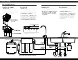
1
This system is designed to be installed under the
sink, but wherever installed, the system requires
access to a cold water supply, a drain line, and
120-volt AC power. Ensure the power supply is
properly grounded and meets all electrical code
requirements. A remote installation should be
close enough so no more than 15' of tubing are
required to run from the RO System and faucet.
The RO System should not be located more
than 10' below the faucet. Excessive distance or
height difference will reduce the flow rate of
the treated water. Depending on the distance
between the system and the faucet, more
tubing may be required to install the system. If
required, use drinking-water rated polyethylene
tubing with a 1/4" outside diameter.
2
Select a location for the RO System Manifold,
the Remineralizer and the Storage Tank.
Temporarily place the components in the
desired location to ensure adequate space
and proper positioning. Allow at least 3" of
clearance between the floor and the bottom
of the filter housings to allow ample space for
filter changes. To help gauge the right location
for the System Manifold, temporarily assemble
the filter housings into the Manifold for
reference.
3
The back plate of the System Manifold includes
two keyhole slots used for hanging the unit on
a wall with (2) #10 mounting screws. The screws
should be threaded into a surface capable
of supporting the weight of the system.
The instructions below assume that you are
mounting the unit to a cabinet wall. If you are
mounting to drywall or a similar surface, use
the appropriate anchors.
4
Mark wall placement for mounting screws using
the diagram below. Ensure that the holes are as
level as possible.
5
Drill two pilot holes for the mounting screws
using a 1/8" drill bit.
6
Insert two #10 screws into the mounting holes,
leaving approximately 3/8" of each screw
exposed.
7
Hang the System Manifold on the mounting
screws. During installation, you can temporarily
remove the unit from the wall to improve
access to various components.
HOT COLD
HOT COLD


