


7
Continued manual resetting of high limit control, preceded by higher
than usual water temperature is evidence of high limit switch operation.
The following is a possible reason for high limit switch operation:
•
A malfunction in the thermostatic controls would allow the gas
valve to remain open causing water temperature to exceed
the thermostat setting. The water temperature would continue
to rise until high limit switch operation.
Contact your dealer or service agent if continued high limit switch
operation occurs.
DIGITAL THERMOSTAT
FIGURE 3
ELECTRONIC IGNITION CONTROL
Each heater is equipped with a Honeywell ignition module. The
solid state ignition control, fig.4, ignites the pilot burner gas by
creating a spark at the pilot assembly. Pilot gas is ignited and
burns during each running cycle. The main burner and pilot gases
are cut off during the OFF cycle. Pilot gas ignition is proven by
the pilot sensor. Main burner ignition will not occur if the pilot
sensor does not first sense pilot ignition.
HONEYWELL IGNITION MODULE
S8600M Continuous Re-Try
FIGURE 4
AUTOMATIC FLUE DAMPER DEVICE
All units are equipped with an automatic flue damper that
reduces heat loss during the OFF cycles. The automatic flue
damper drive assembly is a field replaceable part and may be
obtained by contacting A. O. Smith Water Products Company
at 500 Tennessee Waltz Parkway, Ashland City, TN 37015,
1-800-433-2545. In Canada, contact A.O. Smith Enterprises
LTD., P.O. Box, 310 - 768 Erie Street, Stratford, Ontario, Canada
N5A 6T3, 1-800-265-8520.
Each automatic flue damper drive assembly is equipped with a
“Service Switch”, as shown in figure 5.
FIGURE 5
T h e “ S e r v i c e S w i t c h ” h a s 2 p o s i t i o n s : A U TO M AT I C
OPERATION and HOLD OPEN DAMPER. For normal
o p e r a t i o n t h e s w i t c h s h o u l d b e i n t h e A U TO M AT I C
OPERATION position.
If there is a problem with the damper the “Service Switch”
can be placed in the HOLD OPEN DAMPER position. When
the switch is placed in the HOLD OPEN DAMPER position
the damper disc will rotate to the open position and the
heater may be used until vent assembly is repaired or
replaced. DO NOT turn the damper disc manually; damage
will occur to the drive assembly if operated manually. Refer
to TESTING DAMPER OPERATION section of this manual
for additional information.
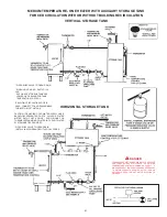
CIRCULATING PUMP
A circulating pump is used when a system requires a circulating
loop or there is a storage tank used in conjunction with the heater.
Refer to the piping diagrams in this manual for electrical hookup
information and install in accordance with the current edition of
the National Electrical Code NFPA 70. For Canada refer to the
Canadian Electrical Code CSA C22.1.
Only all bronze circulators should be used with commercial water
heaters.
Although circulators are oiled and operated by the manufacturer
some circulators must be oiled again before operating. Please
refer to manufacturer’s instructions.
DISHWASHING MACHINE REQUIREMENT
These appliances meet the NSF Standard 5 for sanitary
installations when used with the following leg kits, Part No’s.
6570-0 and 6570-7.
All dishwashing machines meeting the National Sanitation
Foundation requirements are designed to operate with water flow
pressures between 15 and 25 psi (103 kPa and 173 kPa). Flow
pressures above 25 psi (173 kPa), or below 15 psi (103 kPa), will
result in improperly sanitized dishes. Where pressures are high,
a water pressure reducing or flow regulating control valve should
be used in 180°F (82°C) line to the dishwashing machine, and
should be adjusted to deliver water between these limits.
Summary of Contents for BTR 120
Page 25: ...25 FOR NATURAL GAS MODELS...
Page 26: ...26 FOR PROPANE GAS MODELS...


