


30
VENTING SYSTEM
Examine the venting system every six months for obstructions
and/or deterioration of the vent piping.
Remove all soot or other obstructions from chimney which will
retard free draft.
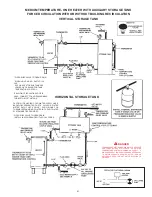
REMOTE STORAGE TANK
TEMPERATURE CONTROL
The water temperature in the storage tank (if used) is controlled
by the storage tank temperature control. The sensing element is
mounted in the hot water storage tank, see page 16.
A change in water temperature in the storage tank lower than the
tank temperature control setting will cause the sensor to activate
the circulating pump. The pump then circulates the water through
the heater where the thermostat senses the drop in water
temperature and activates main burner operation of the appliance.
If the storage tank temperature control is out of calibration, replace
with new control.
WARNING
SHOULD OVERHEATING OCCUR OR THE GAS SUPPLY FAIL
TO SHUT OFF, TURN OFF THE MANUAL GAS CONTROL VALVE
TO THE APPLIANCE.
RELIEF VALVE
At least once a year, the temperature and pressure relief valve
should be checked to ensure that it is in operating condition. Lift
the lever at the top of the valve several times until the valve seats
properly and operates freely.
If the appliance installation includes other relief valves, such as
in “remote” storage tanks etc., check their relief valve operation
with the same frequency.
WARNING
THE WATER PASSING OUT OF THE VALVE DURING THIS
CHECKING OPERATION MAY BE EXTREMELY HOT. AVOID
CONTACT AND DISCHARGE SAFELY TO PREVENT WATER
DAMAGE.
If the temperature and pressure relief valve on the heater
discharges periodically or continuously, a problem exists. This
may be due to unusually high water temperatures or pressures in
the system, or to a faulty relief valve. Contact your dealer or a
qualified service technician to find the cause of the problem and
to correct it. This may also be due to thermal expansion in a
closed water supply system. Contact the water supplier or local
plumbing inspector on how to correct this situation.
DO NOT
PLUG THE TEMPERATURE AND PRESSURE RELIEF VALVE.
WARNING
SHOULD OVERHEATING OCCUR OR THE GAS SUPPLY FAIL
TO SHUT OFF, TURN OFF THE MANUAL GAS CONTROL VALVE
TO THE APPLIANCE.
HOT WATER ODOR
On occasion, hot water may develop a strong odor. If this occurs
drain the heater completely, flush thoroughly, and refill. If the
problem persists, chlorination of the heater and replacement of
the factory installed magnesium anodes with aluminum anodes
may correct the condition.
Occasionally water softener companies recommend removal of
heater anodes for odor reasons.
CAUTION
Unauthorized removal of the anode(s) will void the warranty. For
further information contact your dealer.
ANODE ROD INSPECTION
The heater tank is equipped with anode rods to provide corrosion
control. At least once a year the anode rods should be checked
to determine if replacement is necessary. Initially the anode rods
are approximately 7/8" (22mm) in diameter with a 1/8" (3mm)
diameter steel core wire running down the center of the anode
material. THE ANODES SHOULD BE REPLACED when the 1/8"
(3mm) diameter core wire is visible as this means that the anode
material has been expended in the control of corrosion.
For models with top inlet and outlet, it is recommended that,
before removing the inner cover for cleaning, inspection or
removal of inner parts, you obtain two new nipple collars, part
no. 74060. The nipple collars on the heater will usually be
damaged when removed. New pipe collars will insure that the
seal is such as to prevent leakage of flue products when properly
installed.
NOTE:
Anode rod inspection may need to be made more
frequently in areas subject to acid rain that obtains their water
supply from surface water as the low pH will accelerate anode
activity.
CAUTION:
Close cold water inlet valve serving heater and
open nearby hot water faucet to relieve the pressure in the
heater before attempting to remove anode(s) for inspection.
RECOMMENDED PROCEDURE FOR
PERIODIC REMOVAL OF LIME DEPOSITS
FROM TANK TYPE COMMERCIAL WATER
HEATERS
The amount of calcium carbonate (lime) released from water is in
direct proportion to water temperature and usage, see chart. The
higher the water temperature or water usage, the more lime
deposits are dropped out of the water. This is the lime scale
which forms in pipes, heaters and on cooking utensils.
Lime accumulation not only reduces the life of the equipment but
also reduces efficiency of the heater and increases fuel
consumption.
The usage of water softening equipment greatly reduces the
hardness of the water. However, this equipment does not always
remove all of the hardness (lime). For this reason it is
recommended that a regular schedule for deliming be
maintained.
The time between cleaning will vary from weeks to months
depending upon water conditions and usage.
Refer to A. O. Smith booklet, Form No. 4800, entitled “Why?
When and How” for detailed description on tank inspection and
Summary of Contents for BTR 120
Page 25: ...25 FOR NATURAL GAS MODELS...
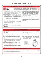
Page 26: ...26 FOR PROPANE GAS MODELS...


