


24
OPERATION
IMPORTANT
A qualified person must perform the initial firing of the heater. At
this time the user should not hesitate to ask the individual any
questions which they may have in regard to the operation and
maintenance of the unit.
An Operational Checklist is included at the rear of this manual.
By using this checklist the user may be able to make minor
operational adjustments and avoid unnecessary service calls.
However, the user should not attempt repairs which are not listed
under the USER column.
GENERAL
NEVER OPERATE THE HEATER WITHOUT FIRST BEING
CERTAIN IT IS FILLED WITH WATER AND A TEMPERATURE
AND PRESSURE RELIEF VALVE IS INSTALLED IN THE RELIEF
VALVE OPENING OF THE HEATER.
SHOULD OVERHEATING OCCUR OR THE GAS SUPPLY FAIL
TO SHUT OFF, TURN OFF THE MANUAL GAS CONTROL VALVE
TO THE APPLIANCE.
CAUTION
Before proceeding with the operation of the unit make sure the
water heater and system are filled with water and all air is
expelled.
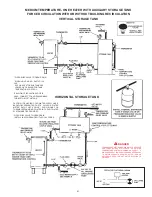
FILLING
1. Close the heater drain valve by turning handle clockwise.
2. Open a nearby hot water faucet to permit the air in the system
to escape.
3. Fully open the cold water inlet pipe valve allowing the heater
and piping to be filled.
4. Close the hot water faucet as water starts to flow.
5. The heater is ready to be operated.
PURGING
Gas line purging is required with new piping or systems in which
air has entered.
CAUTION
PURGING SHOULD BE PERFORMED BY PERSONS
EXPERIENCED IN THIS TYPE GAS SERVICE. TO AVOID RISK
OF FIRE OR EXPLOSION, PURGE DISCHARGE MUST NOT
ENTER CONFINED AREAS OR SPACES WHERE IGNITION CAN
OCCUR. THE AREA MUST BE WELL VENTILATED AND ALL
SOURCES OF IGNITION MUST BE INACTIVATED OR REMOVED.
WARNING
THE GAS VALVE MUST HAVE BEEN IN THE OFF POSITION FOR
AT LEAST 5 MINUTES. This waiting period is an important safety
step. Its purpose is to permit gas that may have accumulated in
the combustion chamber to clear. IF YOU DETECT GAS ODOR
AT THE
END OF THIS PERIOD DO NOT PROCEED WITH
LIGHTING. RECOGNIZE THAT GAS EVEN IF IT SEEMS WEAK,
MAY INDICATE PRESENCE OF ACCUMULATED GAS
SOMEPLACE IN THE AREA WITH RISK OF FIRE OR
EXPLOSION. SEE THE FRONT PAGE FOR STEPS TO BE TAKEN.
All gas and water lines leak tested and open.
With above conditions satisfied, light the unit in accordance with
the instructions on the Operating label attached to the heater. If
label instructions are not legible - determine which gas valve the
appliance is equipped with and use the applicable
OPERATING
INSTRUCTIONS
as follows:
IF PILOT FLAME GOES OUT
- Main burners will extinguish and
pilot will attempt reignition.
DAMPER MUST BE IN FULL OPEN POSITION FOR PILOT AND/
OR MAIN BURNER IGNITION TO OCCUR - See SEQUENCE OF
OPERATION
for complete description.
Each heater is equipped with a Honeywell Ignition Module. This
module will try to prove pilot for 90 seconds. If pilot is not proven
within the 90 secs, the unit will retry after 5 minutes. This cycle
will continue until pilot is proven.
If pilot does not ignite when system calls for heat, check for pilot
ignition spark at pilot assembly.
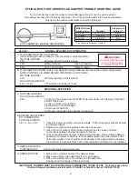
Refer to OPERATIONAL
CHECKLIST and EFFIKAL RVGP-KSF SERIES FLUE DAMPER
TROUBLESHOOTING GUIDE.
Summary of Contents for BTR 120
Page 25: ...25 FOR NATURAL GAS MODELS...
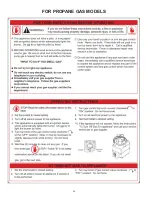
Page 26: ...26 FOR PROPANE GAS MODELS...


