background image

DESCRIPTION 

The 8200 Series Centrifugal Fire Pumps are 
framed mounted pumps which feature – high 
efficiency, rugged construction, compact 
design, foot mounted volute and regreasable 
bearings. These features, along with the 
horizontal split case, make installation, 
operation and service easy to perform. 

OPERATIONAL LIMITS 

Unless special provisions have been made 
for your pump by ITT A-C Fire Pump 
Systems, the operational limits for 8200 
Series Centrifugal Fire Pumps are as follows: 

MAXIMUM WORKING PRESSURE 

Listed on pump nameplate. 

SEAL OPERATING LIMITS 

PACKING 

PH Limitations 7-9; Temperature Range 0 to 
+200°F 

For use on open or closed systems which 
require a large amount of makeup water, as 
well as systems which are subjected to widely 
varying chemical conditions and solids 
buildup. 

PUMP IDENTIFICATION 

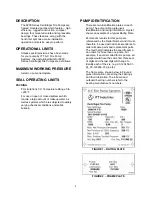
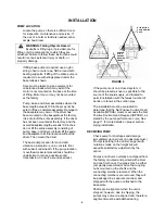
There are two identification plates on each 
pump. The pump rating plate gives 
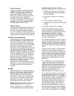
identification and rating information. Figure 1 
shows an example of a typical Rating Plate. 

Permanent records for this pump are 
referenced by the Serial Number and it must, 
therefore, be used with all correspondence to 
order all spare parts and replacement parts. 
The fourth digit indicates the specific pump 
on orders for more than one pump. For 
example, if an order called for six pumps, all 
pumps would have the same first three sets 
of digits and the last digit will change to 
identify each of the six. (e.g. 03-123456-01-
01, 03-123456-01-02, etc.) 

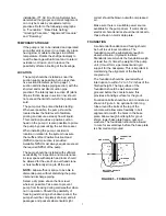
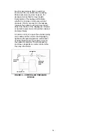
The frame plate, shown below in Figure 2, 
gives information concerning the bearings 
and their lubrication. The inboard and 
outboard bearing numbers refer to the 
bearing manufacturer’s numbers. 


FIGURE 1 – RATING PLATE 


FIGURE 2 – FRAME PLATE 

Summary of Contents for 8200 Series

Page 1: ...1 Instruction Manual AC2675 REVISION A 8200 Series Base Mounted Centrifugal Fire Pumps Installation Operation and Service Instructions INSTALLER PLEASE LEAVE THIS MANUAL FOR THE OWNER S USE ...

Page 2: ... TESTING 17 MAINTENANCE 17 GENERAL MAINTENANCE 17 MAINTENANCE OF PUMP DUE TO FLOOD DAMAGE 17 BEARING LUBRICATION GREASE 18 PACKING SEAL 18 CLEANING WITHOUT DISMANTLING PUMP 18 MAINTENANCE TIME TABLE 19 TROUBLE SHOOTING 20 CHANGING ROTATION 23 SERVICE INSTRUCTIONS 24 DISASSEMBLY AND REASSEMBLY PROCEDURES 24 DISMANTLING PUMP WITH PACKING 24 ASSEMBLY PUMP WITH PACKING 27 APPENDIX A ENGINEERING DATA 3...

Page 3: ...to widely varying chemical conditions and solids buildup PUMP IDENTIFICATION There are two identification plates on each pump The pump rating plate gives identification and rating information Figure 1 shows an example of a typical Rating Plate Permanent records for this pump are referenced by the Serial Number and it must therefore be used with all correspondence to order all spare parts and repla...

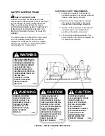
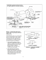
Page 4: ...ulation is required 4 The maximum working pressure of the pump is listed on the pump nameplate do not exceed this pressure FIGURE 3 SAFETY INSTRUCTION DECALS WARNING WARNING CAUTION CAUTION ROTATING COMPONENTS DISCONNECT AND LOCKOUT POWER BEFORE SERVICING DO NOT OPERATE WITHOUT ALL GUARDS IN PLACE CONSULT INSTALLATION AND SERVICE INSTRUCTION SHEET BEFORE OPERATING OR SERVICING FAILURE TO FOLLOW IN...

Page 5: ...low these instructions could result in serious personal injury or death and property damage MECHANICAL SAFETY WARNING Unexpected Startup Hazard Disconnect and lockout power before servicing Failure to follow these instructions could result in serious personal injury or death and property damage WARNING Excessive System Pressure Hazard The maximum working pressure of the pump is listed on the namep...

Page 6: ...cation for sound and vibration ab sorption is on a concrete floor with subsoil underneath If the pump location is overhead special precautions should be undertaken to reduce possible sound transmission Consult a sound specialist FIGURE 4 If the pump is not on a closed system it should be placed as near as possible to the source of the liquid supply and located to permit installation with the fewes...

Page 7: ...e of an overhead crane or hoist sufficiently strong to lift the unit NOTE Allow sufficient space to be able to dismantle pump without disturbing the pump inlet and discharge piping Select a dry place above the floor level wherever possible Take care to prevent pump from freezing during cold weather when not in operation Should the possibility of freezing exist during a shut down period the pump sh...

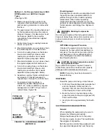
Page 8: ...pletely See Grouting Procedure and allow grout to dry thoroughly before attaching piping to pump 24 hours is sufficient time with approved grouting procedure GROUTING PROCEDURE Grout compensates for uneven foundation distributes weight of unit and prevents shifting Use an approved non shrinking grout after setting and leveling unit See Figure 6 a Build strong form around the foundation to contain ...

Page 9: ...installation Over spreading the guards may alter their fit and appearance Removal a Remove the two capscrews that hold the outer motor side coupler guard to the support bracket s b Spread the outer guard and pull it off the inner guard c Remove the capscrew that holds the inner guard to the support bracket d Spread the inner guard and pull it over the coupler Installation a Check coupler alignment...

Page 10: ... laying a straight edge across one coupler half and measuring the gap between the straight edge and opposite coupler half Up to a 1 64 gap is permissible FIGURE 7A CHECKING ALIGNMENT METHOD 1 INNER GUARD ATTACH SUPPORT BRACKET TO BEARING HOUSING SUPPORT BRACKET BRACKET SUPPORT BRACKET SUPPORT ATTACHED INSIDE HERE IN LINE WITH BOLT CAPSCREW FLAT WASHER SPACER WASHER THIS OPTION USED IN PLACE OF SPA...

Page 11: ...ature When normal operating temperature has been attained secure the pump to re check alignment and compensate for temperature accordingly See Alignment Section WARNING Rotating Components Hazard Do not operate pump without all guards in place Failure to follow these instructions could result in serious personal injury or death and property damage OPTIONAL Alignment Procedure If desired the pump a...

Page 12: ...utions Figure 8 shows some correct and incorrect suction piping arrangements The sizing and installation of the suction piping is extremely important It must be selected and installed so that pressure losses are minimized and sufficient liquid will flow into the pump when started and operated Many NPSH Net Positive Suction Head problems can be attributed directly to improper suction piping systems...

Page 13: ...ollowing precautions a If the pump is operating under static suction lift conditions a foot valve may be installed in the suction line to avoid the necessity of priming each time the pump is started This valve should be of the flapper type rather than the multiple spring type sized to avoid excessive friction in the suction line Under all other conditions a check valve if used should be installed ...

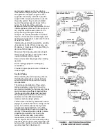
Page 14: ...the MAINTENANCE section of this manual On some applications it is possible to use internal liquid lubrication pumped liquid to lubricate packing Only when all of the following conditions prevail can this be done 1 Liquid is clean free from sediment and chemical precipitation and is compatible with seal materials 2 Temperature is above 32 F and below 160 F 3 Suction pressure is below 75 psig 4 Lubr...

Page 15: ...il only clear liquid drips from the box If the drippage is corrosive or harmful to personnel it should be collected and piped away A common error is to open the external piping valve wide and then control the drippage by tightening the packing gland A combination of both adjustments is essential to arrive at the optimum condition The life of packing and sleeve depends on careful control more than ...

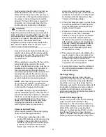
Page 16: ...ng as serious damage can result if the pump is operated with incorrect rotation Check rotation each time the motor leads have been disconnected WARNING Rotating Components Hazard Do not operate pump without all guards in place Failure to follow these instructions could result in serious personal injury or death and property damage CAUTION Seal Damage Hazard Do not run pump dry seal damage may occu...

Page 17: ...used when conducting a field test MAINTENANCE GENERAL MAINTENANCE Operating conditions vary so widely that to recommend one schedule of preventative maintenance for all centrifugal pumps is not possible Yet some sort of regular inspection must be planned and followed We suggest a permanent record be kept of the periodic inspections and maintenance performed on your pump This recognition of mainten...

Page 18: ... is added to avoid overloading NOTE Excess grease is the most common cause of over heating A lithium based NLGI 2 grade grease should be used for lubricating bearings where the ambient temperature is above 20 F Grease lubricated bearings are packed at the factory with Shell Alvania No 2 Other recommended greases are Texaco Multifak No 2 and Mobilux No 2 grease Greases made from animal or vegetable...

Page 19: ...ect the entire piping system Unbolt piping at suction and discharge flanges to see if it springs away thereby indicating strain on the casing Inspect all piping supports for soundness and effective support of load Correct as necessary EVERY YEAR Remove the upper half of the casing Inspect the pump thoroughly for wear and order replacement parts if necessary Check wear ring clearances Replace when ...

Page 20: ...ine and receiving full voltage Frequency may be too low Motor may have an open phase 6 Wrong direction of rotation Check motor rotation with directional arrow on pump casing If rotation is correct with arrow check the relationship of the impeller with casing This will require removing casing upper half See Figure 10 on page 23 7 No rotation Check power coupling line shaft and shaft keys 8 Impeller...

Page 21: ...ed chain a board to suction pipe It will be drawn into eddies smothering the vortex 21 Wrong direction of rotation Symptoms are an overloaded driver and about one third rated capacity from pump Compare rotation of motor with directional arrow on pump casing If rotation is correct with arrow impeller may have to be turned 180 See CHANGING ROTATION 22 System head too high See item 4 23 Defective mec...

Page 22: ...torted by excessive strains from suction or discharge piping Check alignment Examine pump for rubbing between impeller and casing Replace damaged parts Repipe pump 40 Shaft bent due to damage through shipment operation or overhaul Check deflection of rotor by turning on bearing journals Total indicator run out should not exceed 002 on shaft and 004 on impeller wearing surface 41 Mechanical failure...

Page 23: ...t back in the casing and reassemble the pump NOTE The impeller and casing are in the same relationship to each other as they were originally The shaft and motor are also in the same relationship to each other as they were originally The suction and discharge are offset so the piping will need to be changed to accommodate the new flange locations 4 Reassemble the pump and realign the coupling as ca...

Page 24: ...eave valve open and continue Remove the drain plug located on the bottom of the pump housing Do not reinstall plug or close drain valve until reassembly is completed Failure to follow these instructions could result in property damage and or moderate personal injury 1 Drain pump by opening vent plug 2 910 9 and removing drain plugs 2 910 9 on suction and discharge nozzle See Exploded View on page ...

Page 25: ...llers 4 002 0 NOTE Apply heat uniformly to the shaft sleeve to loosen the sealant between the shaft and sleeve CAUTION DO NOT EXCEED 275 F Failure to follow these instructions could result in injury or property damage To further assist in removing the sleeves hold the shaft vertically and drop it on a block of wood The impeller weight should force both the impellers and sleeves from the shaft ...

Page 26: ...URE 11 ASSEMBLY SECTION PUMP WITH PACKING CLOCKWISE ROTATION Dimension A 12 06 FIGURE 12 ASSEMBLY SECTION PUMP WITH PACKING COUNTER CLOCKWISE ROTATION 2ND STAGE IMPELLER 1ST STAGE IMPELLER 2ND STAGE IMPELLER 1ST STAGE IMPELLER ...

Page 27: ...aft rotating the sleeves to evenly distribute the sealant applied in above step Rotate until pin in sleeve engages into keyway of impellers and push sleeves against impeller face until the sleeve is flush against the face Wipe off any excess sealant 8 Place the sleeve O ring 3 914 9 onto shaft and place in sleeve counterbore Verify that dimension A is maintained then using a pin spanner wrench and...

Page 28: ... of the lockwasher tabs into matching slot on the bearing locknut 16 Once bearings are cooled to room temperature coat with 2 to 3 ounces of a recommended grease 17 Slide bearing housings 3 025 3 4 onto shaft over bearings 18 Assemble bearing caps to bearing housings using cap screws 5 904 9 NOTE These are grade 8 screws 19 Assemble pipe plugs 2 910 9 and grease fittings 5 905 9 as required 20 Rep...

Page 29: ...proper gasket compression so no leakage can occur at main joint 28 Slide deflectors toward bearing covers Allow rotating clearance of approximately 1 16 29 Rotate shaft by hand to assure that it turns smoothly and is free from rubbing and binding 30 Cut full rings packing 1 924 9 so that ends butt leaving no gap between packing and casing Install three rings of packing and tap fully to bottom of b...

Page 30: ...acking No Rings Size Square 5 50 5 50 5 50 5 50 5 50 5 50 Seal Cage Width 94 94 94 94 94 94 Shaft Sleeve O D 2 75 2 75 2 75 2 75 2 75 2 75 IMPELLER DESIGN DATA All Dimensions in Inches No of Vanes 6 6 6 6 6 6 Inlet Area Sq Inches 26 75 26 75 33 14 33 14 28 72 28 72 Maximum Diameter 14 0 14 0 14 0 14 0 18 0 18 0 Minimum Diameter 9 0 9 0 9 0 9 0 13 5 13 5 Maximum Sphere 50 50 63 63 63 63 WR for Max ...

Page 31: ...31 APPENDIX B EXPLODED VIEW 8200 SERIES FIRE PUMP CLOCKWISE ROTATION ...

Page 32: ... Shaft 1 3 009 9 Shaft Sleeve 2 3 015 9 Shaft Sleeve Nut 2 5 018 0 Bearing Housing Cover 2 3 025 3 Bearing Housing 1 3 026 3 Bearing Inboard 1 3 026 4 Bearing Outboard 2 5 050 4 Split Ring 1 5 421 4 Retaining Collar 1 3 169 9 Deflector 2 3 177 9 Lip Seal 2 3 516 4 Locknut 1 3 514 4 Lockwasher 1 3 902 9 Set Screw 2 5 904 9 Bearing Cover Bolt 8 3 911 1 Key Impeller 1 3 911 2 Key Coupling 1 3 914 9 O...

Page 33: ...equired Refer to parts list on page 32 for a complete parts list and recommended spare parts Parts should be ordered as far in advance of their need as possible since circumstances beyond the control of ITT A C Fire Pump Systems may reduce existing stock All parts are not carried in stock Some are made for each order If replacement parts required are to be made of different materials than original...

Page 34: ...34 APPENDIX C FIELD TEST REPORT ...

Page 35: ... 4 Pump Efficiency np np BHP x 3960 TDH x GPM 5 Affinity Laws for correcting GPM TDH and BHP for speed RPM 2 1 GPM GPM 2 1 RPM RPM or GPM1 GPM2 x 2 1 RPM RPM 2 1 TDH TDH 2 1 RPM RPM 2 or TDH1 TDH2 x 2 1 RPM RPM 2 2 1 BHP BHP 2 1 RPM RPM 3 or BHP1 BHP2 x 2 1 RPM RPM 3 6 NPSHA DETERMINATION NPSHA Net Positive Suction Head Available NPSHA Atmospheric pressure Vapor pressure of liquid Total suction he...

Page 36: ...INTED IN U S A 11 05 A C Fire Pump 8200 N Austin Avenue Morton Grove IL 60053 Phone 847 966 3700 Fax 847 966 1914 www acfirepump com In Canada Fluid Products Canada 55 Royal Road Guelph Ontario N1H 1T1 Canada Phone 519 821 1900 Fax 519 821 2569 ...

Reviews: