background image

1

2

3

4

1

2

3

4

1

2

3

4

Figure 24

Figure 25

Figure 23

Figure 27

Figure 26

Figure 21

Figure 22

Figure 19

Figure 20

Figure 29

Figure 30

Figure 28

Figure 32

Figure 33

Figure 31

14.4 Steering engine adjustment

When using a UAV, the steering engine adjustment wheel can be used to adjust the direction of the camera:

During flight of the UAV, when the steering engine adjustment wheel turns to the left, the camera will be adjusted 

upward. (Figure 19).

During flight of the UAV, when the steering engine adjustment wheel turns to the right, the camera will be adjusted 

downward. (Figure 20).

APP operation: Click on "More functions" icon (Figure 21) in the APP control interface, it can also switch the aircraft lens 

adjustment (Figure 22).

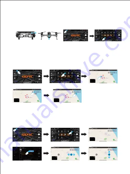
14.5 Waypoint flight mode

 In GPS mode, click "More Functions" icon (Figure 23) in the APP control interface to enter waypoint flight (Figure 

24). At this time, the interface changes from the image transmission page to the map page. On the map page, click 

to set the track range of a single waypoint or continuous waypoints (Figure 25). During the setting process, if the 

track waypoints are too dense, you can click the delete icon to delete all waypoints (Figure 26).

 After setting of the waypoint, click the send icon (Figure 27), the aircraft will fly to all waypoints from the initial point 

to complete the preset flight trajectory. The direction of the aircraft can be controlled by the joystick during the flight.

14.6 Orbital flight mode

In GPS mode, click "More Features" icon in the APP control interface (Figure 28) to enter the orbit flight mode (Figure 

29), the aircraft will automatically orbit in a radius (Figure 30), and the radius can be adjusted on the APP (Figure 31). 

At this time, push the right direction joystick to fly left or right (Figure 32) at the default speed, the orbital speed can be 

adjusted. Push the right direction joystick front or rear, the orbit radius can be adjusted, and when the orbit button is 

pressed again, the orbit flight will end(Figure 33).

10

Summary of Contents for 4D-M1

Page 1: ...aero models and UAV are not allowed to fly within the range of 10 km on each side of center line and 20km on both ends of the airport runway and in the and civil aviation routes and airlines Using va...

Page 2: ...12 Only use the charging cable configured by the factory 13 The charging cable is not a toy 14 When charging the rechargeable battery it must be under the supervision of an adult When charging it must...

Page 3: ...cable for the remote control 1 USB charging cable for the battery 1 3 1 Unscrew the screw and remove the fan blade Note The fan blade is printed with A1 A2 B1 B2 Please install it correctly according...

Page 4: ...battery is charging the green light of the battery flashes from up to down in sequence and the battery power indicator is constantly on when the battery is fully charged The battery is fully charged i...

Page 5: ...of the other end of the USB charging cable to the remote control socket When charging the USB light will be always on and when the battery is fully charged the USB light will go out Tips When the tra...

Page 6: ...ault 30m 20m 2000m Flight altitude default 30m 10m 120m On Off Save Note After being proficient in flight operation it is necessary to close the novice mode and set the flight distance and altitude be...

Page 7: ...er entering and it can also be horizontally calibrated When the APP indicates that the calibration is complete it will automatically proceed to the next step Figure 2 Note The calibration must be comp...

Page 8: ...this time the aircraft can take off normally After taking off all the indicators of the aircraft are always on APP operation Click One Key Unlock icon Figure 6 in APP control interface the one key unl...

Page 9: ...positioning Refer to 12 9 Start stop the normal mode needs to be turned on for the indoor operation refer to 12 10 13 Control method APP operation Enter the APP control interface and click the joysti...

Page 10: ...ove the geomagnetic calibration position Figure 14 The aircraft will automatically rise to a safe altitude when it is flying below the safe altitude and then land slowly If there are obstacles during...

Page 11: ...hanges from the image transmission page to the map page On the map page click to set the track range of a single waypoint or continuous waypoints Figure 25 During the setting process if the track wayp...

Page 12: ...n Figure 34 in the APP control interface to enter the follow mode Figure 35 the aircraft will automatically move by tracking changes in the location of the mobile device mobile phone or IPAD of the co...

Reviews: