background image


-

- 39 --


3S


E-Class NVR


V1.0.0.0 


Required cables and interface card 

1.

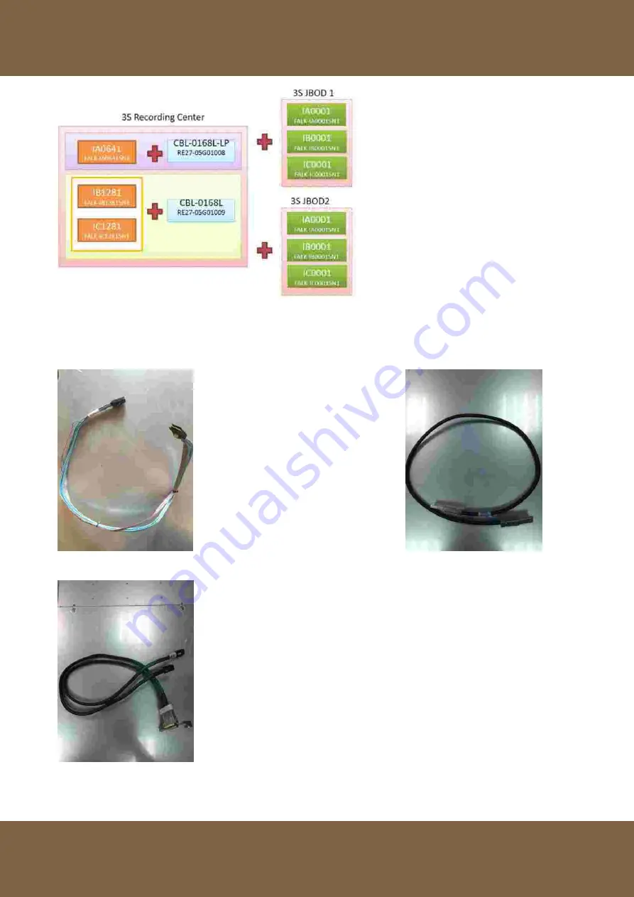
 Install RAID card in NVR backplane and install cable CBL-0281L   2. Connect NVR 

and JBOD with cable CBL-0166L 


3. NVR RAID card internal cable CBL-352L 


NVR Internal Wiring Instructions


Summary of Contents for IA0641

Page 1: ...E Class HD NVR IA0641 IB1281 IC1281 E Class HD NVR Server V1 0 Manual ...

Page 2: ...le of Content Revision 2 Terms and Conditions 3 Product Contents 3 Symbols Used in This Manual 3 Hardware Installation and Parameter Settings 4 How to Create a RAID Group in LSI WEB BIOS 18 How to create hot spare in LSI WebBIOS 32 ...

Page 3: ...troller failure 3S strongly recommends that all data be periodically backed up 3S does not assume any responsibility for data loss or recovery 2 Shut down the system from Windows Do not disconnect the power while system is running Sudden loss of power can result in inconsistencies in stored data Normal shut down process ensures all data is written to disk before shut down ...

Page 4: ...nality of 3S products The HDRC NVR uses Windows 7 for the operating system Users only need to connect keyboard mouse storage drives power and network cables The NVR comes preinstalled with all required software no need to install additional software Product Contents NVR Server IA0641 IB1281 IC1281 Qty 1 Power Cord Qty 2 System Restore USB Qty 1 Screw Package Qty 1 and Rack Rails Qty 2 Symbols Used...

Page 5: ... case of failure HDRC supports remote viewing from the Internet using 3VMS mobile application Using the E Class NVR with HDRC recording software coupled with 3S vision cameras HDCC client software and 3VMS mobile application provides a complete security solution with a variety of applications Equipment Specifications and Operations E Class NVR uses Windows 7 Embedded for the operating system E Cla...

Page 6: ...e following safety instructions Use a CE UL BSI safety certified power cord for the E Class NVR server Do Not expose system to harsh humid environments Electrical installation regulations must be followed All maintenance work must follow 3s provided troubleshooting steps Please read this manual before installing or operating the system This document contains important safety instructions regarding...

Page 7: ...Dispose of used batteries according to the manufacturer s instructions Electrical Shock Hazard Redundant Power Supplies This unit might have more than one power supply connection All connections must be removed to de energize the unit Electrical Shock Hazard Backplane Voltage Hazardous voltage or energy is present on the backplane when the system is operating Use caution when servicing Electrical ...

Page 8: ...check for an inoperative fan Blinking Red 0 25 Hz Power failure check for non operational power supply Solid Blue Local UID has been activated Use this function to locate the server in a rack mount environment Blinking Blue 300 msec Remote UID is on Use this function to identify the server from a remote location NIC2 Indicates network activity on GLAN2 NIC1 Indicates network activity on GLAN1 HDD ...

Page 9: ...he JBOD To perform most maintenance tasks unplug the system to remove all power Drive Carrier LEDs Blue Light Solid light indicates normal operation Flashing light indicates data activity Red Light Solid light indicates drive failure Flashing light indicates hot spare Rear of Device Video stream input Video stream forwarding Audio input output RAID Interface Card USB 3 0 and 2 0 AC100 240V 50 60Hz...

Page 10: ...tion if installed in closed or multi unit rack assembly the ambient operating temperature of the rack environment may be greater than the ambient temperature of the room Therefore consideration should be given to installing air conditioning and ensuring fans in the server racks are providing sufficient air flow Note Please refer to the 3S official website for specifications to help select a cabine...

Page 11: ...he rail locking tabs engage to prevent the server from being overextended Have a rack lift in place as a precaution in case the test fails The following step is the mounting screws and retaining clips 1 Pull the inner rail out of the outer rail until it is fully extended press the locking tab to release inner rail pull the inner rail all the way out Pull External Side Middle Front Side ...

Page 12: ...e of the chassis aligning the hooks of the chassis with the inner rail holes Make sure the rail faces outward so that it will fit with the rack s mounting bracket Slide the rail toward the front of the chassis to hook the inner rail onto the side of the chassis Secure the rail with two flat head screws Screw Screw ...

Page 13: ... the locking tab at the rear end of the middle rail Push the middle rail back into the outer rail 4 Hang the hooks on the front of the outer rail onto the square holes on the front of the rack Use screws to secure the outer rails to the rack Screw ...

Page 14: ... 13 3S E Class NVR V1 0 0 0 5 Pull out the rear of the outer rail adjusting the length until it just fits within the posts of the rack ...

Page 15: ...ides You may have to depress the locking tabs on both sides while inserting When the server has been pushed completely into the rack the locking tabs should click into the locked position Middle Slide Press the latch on both sides of the front slide rail at the same time to push the NVR server into the cabinet ...

Page 16: ... 15 3S E Class NVR V1 0 0 0 7 Optional Insert and tighten the thumbscrews that hold the front of the server to the rack Tighten Screw Tighten Screw Completed ...

Page 17: ...ision official site to check compatibility list to avoid incompatibility http www 3svision com tw source nvr e class hdd compatibility list html 1 Press the dark purple release button on the drive carrier This extends the drive carrier handle Use the handle to pull the drive out of the chassis ...

Page 18: ... carrier and remove the dummy drive Dummy Drive Drive Carrier Take ESD precautions to avoid damage to hard disk 3 Secure the hard drive to the carrier using six screws Replace the drive carrier into the chassis Make sure to close the drive carrier handle to lock the drive carrier into place ...

Page 19: ...r to the RGB or HDMI connector Connect the network cables to the network card for video input and video output 3 Ensure both power cables are securely connected to the NVR power supplies System Settings How to Create a RAID Group in LSI WEB BIOS 1 Press power button to start NVR server 2 While the host computer boots hold the Ctrl key and press the H key when the following appears Copyright LSI Lo...

Page 20: ... 19 3S E Class NVR V1 0 0 0 3 Choose option Configuration Wizard 4 Select the option New Configuration and then click Next to continue ...

Page 21: ...ion and erase data Click Yes to erase all configuration and continue 6 Select option Virtual Drive Configuration and click Next to continue 7 Select the drives to include in the Drive Group and click the Add to Array button Note Make sure not to select the Backplane it will cause an error ...

Page 22: ... 21 3S E Class NVR V1 0 0 0 8 When finished adding hard drives to the hard drive group click the Accept DG button See illustration below ...

Page 23: ... 22 3S E Class NVR V1 0 0 0 9 Click the Next button to continue ...

Page 24: ... 3S E Class NVR V1 0 0 0 10 Click Add to SPAN button to add drive group to SPAN then click the Next button to continue 11 Select the RAID level RAID 0 RAID 5 or RAID 6 Note 3S recommends RAID 5 6 for data ...

Page 25: ...ip size 64kb access policy RW Read Policy Ahead Write Policy Write through IO policy Direct Drive Cache NoChange Disable BGI No After selecting RAID level and modifying RAID settings click the Accept button to save changes Press the Next button to continue 12 Click Yes button to confirm Write Through mode to continue ...

Page 26: ...S E Class NVR V1 0 0 0 13 After confirming write through mode the Virtual Drive screen will show then click the Next button to continue Note Ignore RAID level 0 14 Click Yes button to save the configuration ...

Page 27: ...NVR V1 0 0 0 15 Select the new virtual drive group select Fast Initialize option then click the Go button to initialize the virtual drive group Click Yes button to confirm data loss and to proceed with initialization ...

Page 28: ...1 0 0 0 16 After configuration is complete the newly configured virtual drives will show in LSI WebBIOS screen Click Exit to leave LSI WebBIOS configuration utility 17 When the JBOD reboots it shows the new Virtual Drive s ...

Page 29: ... Disk management will show the new virtual drive group right click on the unallocated drive and select Initialize Disk 19 The Initialize Disk window will show and automatically select GPT format when the storage space is greater than 2TB Click OK button to complete initialization of disk GPT ...

Page 30: ... 29 3S E Class NVR V1 0 0 0 20 After initialization is complete right click on the disk and create a new volume 21 Click Next button on the New Simple Volume Wizard to continue ...

Page 31: ... 22 Enter the storage space for the new volume The default size is the maximum size of the disk group 23 Select the file system type NTFS and Allocation unit size Note 3S recommends using the Default Allocation unit size default ...

Page 32: ...0 24 Click the Finish button to complete the New Volume Wizard 25 After completing the new volume wizard the new volume will automatically start formatting in the background The drive status shows Healthy after format completion ...

Page 33: ...ta can only be reconstructed from RAID levels with data redundancy Hot spare requirements 1 Use the same model and brand of hard drive as the original drives in the volume set 2 If same model drive is not available ensure the replacement drive speed matches the original 3 Confirm the replacement hard drive is listed on 3S visions hard drive compatibility list Make sure there is enough storage spac...

Page 34: ... 33 3S E Class NVR V1 0 0 0 Select Make Global HSP to make hard drive hot spare Click the Go button to confirm change ...

Page 35: ...VR then press the Del key during the boot process to enter the BIOS menu After entering the BIOS screen select the Boot tab then set Boot Option 1 to USB drive Click the Save Exit tab or press F10 to save configuration and exit BIOS screen 2 After NVR reboot it will detect the USB drive and boot to Windows 7 setup interface ...

Page 36: ...E Class NVR V1 0 0 0 Select the 64G SATA DOM drive to install Windows 7 Embedded OS Must select the 64G SATA DOM drive that came with the server to install Windows OS on Click Next to complete the installation ...

Page 37: ...ml Note 3S Vision is not responsible for hard drive performance Please contact HDD manufacturer to resolve issues with HDD performance 2 If the video still will not record please provide the following information 2 1 Networking environment 2 2 Hard drive brand and model Listed on HDD label 3 Please follow instructions to complete the RAID configuration settings Please refer to How to Create a RAID...

Page 38: ...ional Depending on which type of connection is used either serial or parallel will determine the type of SAS interface card to buy for the NVR See illustration bellow Note 1 E Class NVR support 2 JBODs for expansion Serial Connection Method Required cables and interface card 1 Install RAID card in NVR backplane and install cable CBL 0281L 2 Connect NVR and JBOD with cable CBL 0166L 3 NVR RAID card...

Page 39: ...ane PRI_J1 2 Internal SAS cable CBL 0167L Connects to the SAS interface on the RAID card Server and JBOD external SAS connections 1 Use the SAS external cable CBL 0166L to connect the Server OUT Data Input side to the JBOD_1 IN Data Out side 2 Use SAS external cable CBL 0166L connection JBOD_1 OUT data input End and JBOD_2 IN data output side Parallel Connection Method ...

Page 40: ... 0 0 0 Required cables and interface card 1 Install RAID card in NVR backplane and install cable CBL 0281L 2 Connect NVR and JBOD with cable CBL 0166L 3 NVR RAID card internal cable CBL 352L NVR Internal Wiring Instructions ...

Page 41: ...S interface on the RAID card 3 The SAS connector on the same internal SAS cable CBL 0352L and the SAS connector on the backplane PRI_J2 Server and JBOD external SAS connections 1 Use the SAS external cable CBL 0166L to connect the OUT data input side of the server JBOD_1 IN data output side 2 Use the SAS external cable CBL 0166L to connect the OUT data input side of the JBOD_2 IN data output side ...

Reviews: