


- 4 -
100m) according to reasonable scheme.
4. Power: 48VDC power input
5. Environment: Working temperature: -40
~
70
℃
Storage temperature: -40
~
85
℃
Relative humidity: 5%
~
95%
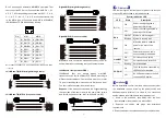
DIN Rail Installation
In order to use in industrial environments expediently, the
product adopt 35mm DIN-Rail installation, the installation
steps as below:
1. Examine the DIN-Rail attachment
2. Examine DIN Rail whether be firm and the position is
suitability or not.
3. Insert the top of the DIN-Rail into the slot just below the
stiff metal spring.
4. The DIN-Rail attachment unit will snap into place as
shown below.
Wiring Requirements
Cable laying need to meet the following requirements,
1. It is needed to check whether the type, quantity and
specification of cable match the requirement before
cable laying;
2. It is needed to check the cable is damaged or not, factory
records and quality assurance booklet before cable
laying;
3. The required cable specification, quantity, direction and
laying position need to match construction requirements,
and cable length depends on actual position;
4. All the cable cannot have break-down and terminal in the
middle;
5. Cables should be straight in the hallways and turning;
6. Cable should be straight in the groove, and cannot
beyond the groove in case of holding back the inlet and
outlet holes. Cables should be banded and fixed when
they are out of the groove;
7. Pigtail cannot be tied and swerved as less as possible.
Swerving radius cannot be too small (small swerving
causes terrible loss of link). Its banding should be
moderate, not too tight, and should be separated from
other cables;
8. It should have corresponding simple signal at both sides
of the cable for maintaining.
【
Specification
】
Technology
Standard: IEEE802.3, IEEE802.3u, IEEE802.3z/ab,
IEEE802.3af/at, IEEE802.3x, IEEE802.1Q, IEEE802.1p,
IEEE802.1W/D, IEEE802.1s, IEEE802.3ad,
IEEE802.1X
Protocol: ARP, ICMP, TCP, DHCP, DNS, HTTP, Telnet,
SW-Ring, RSTP, MSTP, LLDP, SSH, LACP, ACL, IGMP,
GMRP, SNMP
Flow control: IEEE802.3x flow control, back press flow
control
Function
Switch function: POE, SW-Ring, QOS, 802.1QVLAN, RSTP,
MSTP, LLDP, LACP, ACL, ROMN, GMRP, IGMP
Snooping, SNMP, Port trunking, static multicast filter,
port mirroring, bandwidth management, broadcast
storm control, port flow statistics, upgrade online, up
and download configuration file, user name access
system
SW-Ring: Support Single, Couple, Chain, Dual homing
Exchange attribute
100M forward speed: 148810pps
1000M forward speed: 1488100pps
Transmit mode: store and forward
System exchange bandwidth: 24Gbps
MAC address table: 8K
Memory: 4Mbit
Interface
Gigabit RJ45 port: 10/100/1000BaseT(X)
auto speed control,
Half/full duplex and MDI/MDI-X auto detect
PoE Pin-out: 1/2(+), 3/6(-)
Gigabit SFP port: 1000Base-X, SFP slot
Console port: RS-232 (RJ45 connector)
Alarm port: 2 bit terminal block
1 channel relay alarm output
Current load capacity 1A@24VDC
Transfer distance
Twisted cable: 100M (standard CAT5e/CAT6 cable)
Multi-mode: 1310nm, 2Km
Single-mode: 1310nm, 20/40Km
1550nm, 60/80/100/120Km
LED indicator
Run indicator: RUN
Power supply indicator: P1, P2
Alarm indicator: ALM
Interface indicator: Link (1~12)
POE indicator: POE(1~8)
Power supply
Input Voltage: 48VDC
Type of input: 4 bits 7.62mm terminal block
DC support reverse connection protection


