


- 2 -
Front view Side view
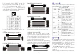
1. Ground screw
2. Terminal block for relay output
3. Console port
4. Terminal block for power input (PWR1, PWR2)
5. DIP switches
6. DIN-Rail mounting kit
7. System running indicator
8. Relay alarm indicator
9. Power input P1(P2) LED
10. PoE port Link/ACT indicator
11. Ethernet port Link/ACT indicator
12. Gigabit PoE port
13. Gigabit SFP port
【
Power supply input
】
The product top panel provided 4 bit power supply input
terminal block, support DC input. DC power supply input
supported redundancy function, provided PWR1 and PWR2
power input, can use for single, and can connect 2
separately power supply system, use 1 pair terminal block
connect the device at the same time. If one of the power
systems broke, the device can work un-interruptible. Built-in
overcorrect protection, Reverse connection protection.
Voltage input range is 48VDC (terminal block defined as:
V1-
、
V1+
、
V2-
、
V2+). The power supports reverse connection
protection.
【
Dimension
】
Unit (mm)
【
Relay connection
】
Relay access terminals in the top panel of the device.
Between the two terminal relay, as an open circuit state in
normal non alarm state, when there is power alarm
information to the closed state. The two terminal block
connector are used to detect power failure and network
anomaly. The two wires attached to the Fault contacts form
a closed circuit when the device port connection disconnect
or has lost power supply from one of the DC power inputs.
The user can connect the relay to the lamp indicate or
buzzer alarm to remind the relevant staff.
【
Console port
】
This series product provided 1pcs procedure test port based
in serial port. It adopts RJ45 interface, located in top panel,
can configure related command through RJ45 to DB9
female cable.
【
DIP Switch
】
Top panel provided 4 bits DIP switch to do function configure
(ON to enable effective), 1 and 4 keep for future function. 2
is recovery default factory. 3 is for upgrade. Please power off
and power on when you change the status of DIP switch.
【
Communication connector
】
10/100/1000BaseT(X) Ethernet port
The pinout of RJ45 port display as below, connect by UTP or
STP. The connect distance is no more than 100m.
1000Mbps is used 120Ω
of UTP 5e; 100Mbps is used 120Ω
of UTP 5; 10Mbps is used 120Ω of UTP 3, 4, 5.


