


- 3 -
RJ 45 port support automatic MDI/MDI-X operation. That
can connect the PC, Server, Converter and HUB. Pin 1, 2, 3,
4, 5, 6, 7, 8 Corresponding connections in MDI. 1→3, 2→6,
3→1, 4→7, 5→8, 6→2, 7→4, 8→5, are used as cross wiring
in the MDI-X port of Converter and HUB. In MDI/MDI-X,
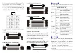
100/1000Base-TX PIN defines is as follows:
1
8
PIN
MDI
MDI-X
1
BI_DA+/TX+ BI_DB+/RX+
2
BI_DA-/TX-
BI_DB-/RX-
3
BI_DB+/RX+ BI_DA+/TX+
4
BI_DC+/—
BI_DD+/—
5
BI_DC-/—
BI_DD-/—
6
BI_DB-/RX-
BI_DA-/TX-
7
BI_DD+/—
BI_DC+/—
8
BI_DD-/—
BI_DC-/—
Note: 10Base-T/100Base-TX, “TX±”transmit data±, “RX±”receive data±,
“—”not use.
10/100Base-T(X) MDI (straight-through cable)
10/100Base-T(X) MDI-X (Cross over cable)
Gigabit MDI (straight-through cable)
Gigabit MDI-X (Cross over cable)
MDI/MDI-X auto connection makes switch easy to use for
customers without considering the type of network cable.
1000Base-X fiber port(mini-GBIC)
1000Base-X fiber port adopts gigabit mini-GBIC
transmission, can choice different SFP module according to
different transfer distance. Fiber interface must use for pair,
TX port is transmit side, must connect to RX (receive side).
The fiber interface support loss line indicator.
Suppose
: If you make your own cable, we suggest labeling
the two sides of the same line with the same letter (A-to-A
and B-to-B, shown as below, or A1-to-A2 and B1-to-B2).
【
LED Indicator
】
LED indictor light on the front panel of product, the function
of each LED is described in the table as below.
System indication LED
LED
State
Description
P
(1~2)
ON
Power is being supplied to
power input PWR input
OFF
Power is not being supplied to
power input PWR input
RUN
ON/OFF System is not running well
Blinking System is running well
ALM
ON
When the alarm is enabled,
power or the port’s link is
inactive.
OFF
Power and the port’s link is
active, the alarm is disabled.
Link/ACT
(1~12)
ON
Port connection is active
OFF
Port connection is not active
Blinking Data transmitted
POE(1~8)
ON
The PoE device is connected by
IEEE802.3af/at standard
OFF
No PoE power output or no PoE
connected PoE devices
【
Installation
】
Before installation, confirm that the work environment meet
the installation require, including the power needs and
abundant space. Whether it is close to the connection
equipment and other equipments are prepared or not.
1. Avoid in the sunshine, keep away from the heat
fountainhead or the area where in intense EMI.
2. Examine the cables and plugs that installation
requirements.
3. Examine whether the cables be seemly or not (less than


