background image

3D Systems, Inc.

20

D

Device Registration Methods

Registers the position of connected devices or aligns scans into one coordinate system with various registration methods.
The following table shows how the each registration method calculates a transform matrix from scans.
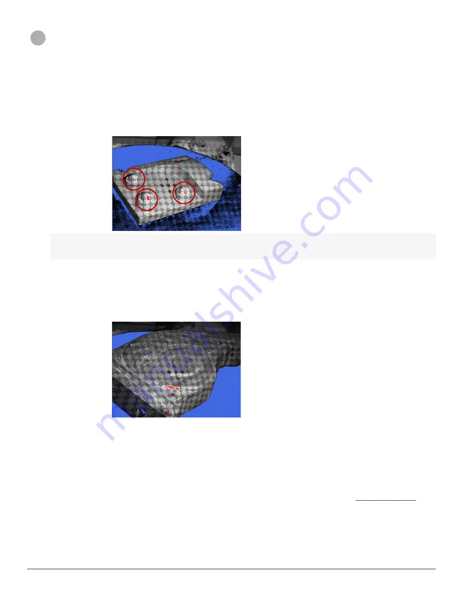
Spheres

After detecting the center point of spherical features from scans scanned from each connected scanner, 

calculates a transform matrix so that the distance between the corresponding reference points is 

minimized, and then uses the transforms for registering the position of the devices or for aligning scans 

into one coordinate system.

Note: To register the position of connected devices with the Spheres registration method, an object 

requires to be positioned so that at least three spherical features can be matched between scans 

and must be visible in the camera view of each connected scanner while setting up the device 

registration.

Best Fit

Calculates a transform matrix by aligning scans scanned from each connected scanners with the best-fit 

alignment method and uses the transforms for registering the position of the 

devices

 or for aligning scans 

into one coordinate system. 

Target Markers

After detecting target markers from scans scanned from each connected scanner, calculates a transform 

matrix so that the more than four scanned target markers can be matched, and then uses the transforms 

for registering the position of the 

devices

 or for aligning scans into one coordinate system.

Note: To register the position of connected devices with the Target Markers registration method, an 

object requires to be positioned so that at least four target markers can be matched between scans 

and must be visible in the camera view of each connected scanner while setting up the device 

registration.

Note: When using the device registration methods, refer to the tips below:

• 

Prevent the scan floor from being captured in a scan

• 

Apply white scanning spray or powder evenly and make sure an object is adequately covered

• 

Dim the lights

• 

Use proper sized target markers

For more information on how to get better device registration and scan alignment results, see 

3D Scanning Basics

.

Current Location 

- Registers the position of connected 

devices

 by using the transform matrix calculated from the last scan 

alignment. If you already have scans aligned with the other alignment methods provided in your Geomagic application, you can 

update it to the Geomagic Capture.

Register

 - After scanning an object with the selected registration method, and then uses the transforms for registering the 

position of connected 

devices

 or for aligning scans into one coordinate system.

Summary of Contents for Geomagic Capture Series

Page 1: ...Harness the Power of 3D Scanning Geomagic Capture User Guide Geomagic Capture Series 3D Scanner for 3D Scan Based Design and Quality Inspection...

Page 2: ...CIFICATIONS 5 SYSTEM REQUIREMENTS FOR GEOMAGIC CAPTURE APPLICATION 5 4 3D SCANNING BASICS 6 5 SETTING UP GEOMAGIC CAPTURE SERIES 3D SCANNER 8 6 CREATING SCAN DATA 11 SCAN AN OBJECT AND CREATE SCAN DAT...

Page 3: ...tion tools in a seamless push button manner With unprecedented performance and affordability Geomagic Capture ushers in a new era of design to manufacturing productivity and utility Harness the Power...

Page 4: ...publication As more definitively stated and set forth in the License Agreement 3D Systems Inc does not and will not accept any financial or other responsibility that may result from use of the Softwar...

Page 5: ...optimal results G Exposure Settings Allows users to adjust an exposure value H Turntable Settings Allows users to adjust the number of scan divisions in 360 rotational degrees I Status Bar Shows the...

Page 6: ...Inc 4 Advanced Settings A Device Status Manages device connection status B Network Configuration Configures the network to communicate with scanners C Update Device Firmwares Updates device firmwares...

Page 7: ...r End mm 124 x 120 mm Near 190 x 174 mm Far 87 x 68 mm Near 88 x 87 mm Far Calibration Pre calibrated Note It is not recommended that you use scanner setup mixed with different type of the Geomagic Ca...

Page 8: ...e scanner so it can capture as much of the object as possible while remaining perpendicular to the object s surface Line of sight The scanner can capture only what is in its line of sight If you scan...

Page 9: ...ts spray deodorant with titanium oxide and tempera paint from a compressor You must spray the part with a uniform light coat The thinner the coating the better Adding more than a thin coat of white po...

Page 10: ...e check if all cables and cordsets are connected to the scanner and the PC and then click OK to reconnect the scanner 4 The Geomagic Capture application will initiate Select the check box next to the...

Page 11: ...tion point in a network the IP address of the network adapter in your PC should be the same as a default gateway of the device and the subnet mask of the network adapter should be the same as the subn...

Page 12: ...tarted up You can simply update the device firmware by clicking OK in the message Note If there is an issue with updating the device firmware you must use the manual device firmware update to control...

Page 13: ...posure is set to the conditions Stability of the scanner and the object If either the scanner or the object move during the scan the data will be inaccurate Ensure both are stable and se cure Shape an...

Page 14: ...stration methods for the scanners then click Register Note If a part has spherical features more than three for example you can register the position of the scanners into one coordinate system with th...

Page 15: ...to the Scan menu by clicking Back 12 Reposition the part and click Scan to take another scan Note If a scan was made using the Best Fit alignment method make sure at least 30 of the original scan area...

Page 16: ...elect the desired registration method then click Register The application will automatically take scans by rotating the plate in a certain degree then will calibrate the turntable by aligning the scan...

Page 17: ...may have difficulty matching target markers and fail to align scans Please ensure the target markers are placed so cameras can see them even though the part is moved Note To align two scans at least...

Page 18: ...d then go to Settings by clicking Settings to update the transforms to the application e In the Device Registration select Current Location then click Register to update the transforms that has been c...

Page 19: ...part D Starting Position of Rotational Scanning Indicates the starting point of rotational scanning from 0 to 360 rotational degrees E Scanning Button Starts the scanning This button is available afte...

Page 20: ...blue and black is under exposed An optimal scan has a good balance and several high spots of exposure Under Exposed Over Exposed Optimal Note Scan quality can vary by the following factors Environmen...

Page 21: ...an exposure value A scan that shows a lot of red is over exposed and a scan that shows a lot of blue and black is under exposed This option is linked with the Exposure option in the Scan menu Under E...

Page 22: ...s scanned from each connected scanner calculates a transform matrix so that the more than four scanned target markers can be matched and then uses the transforms for registering the position of the de...

Page 23: ...3D Systems Inc 21 E Advanced Options Opens the Advanced Settings menu F Back Goes back to the Scan menu G Help Shows the Help document...

Page 24: ...ice Status Auto Configure Automatically reconfigures the network for all checked scanners IP Address Used to manually set a static IP address Subnet Mask Default Gateway Used to manually set a subnet...

Page 25: ...3D Systems Inc 333 Three D Systems Circle Rock Hill SC 29730 www 3dsystems com 2014 3D Systems Inc All rights reserved...

Reviews: