


48
C
HAPTER
7: S
WITCH
F
ABRIC
M
ANAGEMENT
M
ODULES
AND
I
NTERFACE
M
ODULES
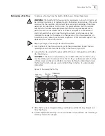
Installation
If you install two Switch Fabric Management Modules (in slot M1 and M2), your
system has redundancy in both management and system controller functions.
When you power on or reboot the system with two SFMMs installed, the module
in slot M1 becomes the
primary
SFMM and the module in slot M2 becomes the
secondary
SFMM. However, if you install an SFMM while the system is powered
on, the first module installed becomes the primary SFMM and second module
installed becomes the secondary SFMM.
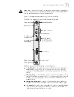
The Primary LED will light up on the module your system has assigned as the
Primary SFMM.
The Relationship
Between Two
Management Modules
The system categorizes the two SFMMs as primary and secondary management
entities. The secondary module operates in
hot standby mode
, which means that it
is constantly kept informed about the dynamic state of the management activities
that are occurring on the primary SFMM.
The system treats both SFMMs as a single logical device. The primary SFMM and
the secondary SFMM become synchronized after redundancy is established. When
any configuration or non-volatile data is modified on the primary SFMM, the data
is automatically modified on the secondary SFMM. Thus, if the primary SFMM fails
for any reason, the secondary SFMM immediately takes over all primary functions.
The Failover Process
If you remove (deinstall) the primary SFMM or if the module fails in some way, the
following process occurs automatically:
1
The system initiates the fail-over mechanism (after, for example, the primary
module fails or is removed).
2
The system reboots and the secondary SFMM becomes the primary SFMM.
Because it learned all the configuration settings from the primary SFMM, it
continues to provide all the management functions.
3
If you remove a failed SFMM that used to be primary and install a new SFMM in
that slot, the new module remains secondary and starts duplicating all
configuration information.
If, after the failover occurs, the failed SFMM recovers to a normal operating
condition, it will remain in the secondary state. The failover mechanism is
non-revertive. Even if the problem that caused the failover is resolved, the failover
process does not switch the primary state back to the original primary SFMM
unless the system is rebooted.
Connectivity Rules
The following connectivity rules apply after you establish SFMM redundancy:
■
You cannot access the secondary SFMM through its console port. Console
management is only available through the primary SFMM.
■
You cannot Telnet to the secondary SFMM from an external source because
both the primary SFMM and the secondary SFMM share the same IP address
for the Switch. Therefore, when you attempt to Telnet to the shared IP address,
you always access the primary SFMM.
Summary of Contents for 4005
Page 28: ...28 CHAPTER 4 SWITCH 4005 CHASSIS ...
Page 36: ...36 CHAPTER 5 SWITCH 4005 POWER SUPPLIES ...
Page 76: ...76 GLOSSARY ...


