


24
C
HAPTER
4: S
WITCH
4005 C
HASSIS
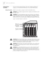
Install the chassis before you install the cable management device, but plan ahead
so that there will be sufficient space for the cable management device on the rack.
NOTE:
If your rack has a door, you may have to leave the door open to provide
space for the cable management device and the cabling.
Installing the Chassis
This section describes how to install the chassis in a rack (with or without clip
nuts), on a table, or on a shelf. See the section that applies to your installation:
■
Rack Installation
■
Table or Shelf Installation
Rack Installation
Using at least two people, follow these steps to mount the chassis in a rack:
Some steps in the next procedure mention clip nuts. All racks do not require the
use of clip nuts. Consult your rack documentation. (Note: Clip nuts are not
provided in the Switch 4005 hardware kit.)
1
Read the previous section in this chapter titled “Preinstallation Guidelines” as well
as the all sections that discuss safety information.
2
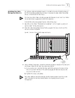
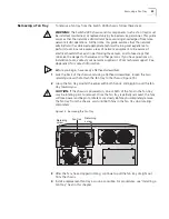
Using eight of the smaller screws and the flanges from the hardware kit, attach
the flanges to the chassis (four screws per flange) as shown in Figure 5.
Figure 5 Attaching a Flange to the Chassis
3
Locate and mark the holes on the rack where you want to mount the chassis.
4
If applicable, position clip nuts on the rack. See Figure 6.
Rack-mount
flange
Summary of Contents for 4005
Page 28: ...28 CHAPTER 4 SWITCH 4005 CHASSIS ...
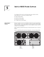
Page 36: ...36 CHAPTER 5 SWITCH 4005 POWER SUPPLIES ...
Page 76: ...76 GLOSSARY ...


