background image

I

S

WITCH

 F

EATURES

Chapter 1

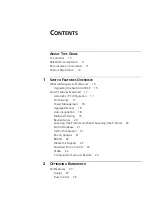
Switch Features Overview

Chapter 2

Optimizing Bandwidth

Chapter 3

Using Multicast Filtering

Chapter 4

Using Resilience Features

Chapter 5

Using the Switch Database

Chapter 6

Using Traffic Prioritization

Chapter 7

Status Monitoring and Statistics

Chapter 8

Setting Up Virtual LANs

Chapter 9

Using Webcache Support

Chapter 10

Using Automatic IP Configuration

Chapter 11

Making Your Network 
Secure

Chapter 12

Power 
Management 
and Control

Summary of Contents for 3C17205-US - Corp SUPERSTACK 3 SWITCH 4400...

Page 1: ...http www 3com com Part No DUA1720 3BAA04 Published January 2003 SuperStack 3 Switch Implementation Guide Generic guide for units in the SuperStack 3 Switch 4400 Series 3C17203 3C17204 3C17205 3C17206...

Page 2: ...y portion of any legend provided on any licensed program or documentation contained in or delivered to you in conjunction with this User Guide Unless otherwise indicated 3Com registered trademarks are...

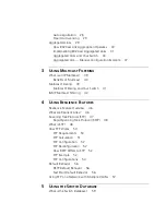
Page 3: ...Automatic IP Configuration 17 Port Security 17 Power Management 18 Aggregated Links 18 Auto negotiation 18 Multicast Filtering 19 Resilient Links 20 Spanning Tree Protocol and Rapid Spanning Tree Prot...

Page 4: ...our Switch 41 IGMP Multicast Filtering 42 4 USING RESILIENCE FEATURES Resilience Feature Overview 46 What are Resilient Links 46 Spanning Tree Protocol STP 47 Rapid Spanning Tree Protocol RSTP 48 What...

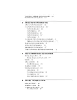
Page 5: ...ring Traffic Prioritization 72 Important QoS Considerations 72 Default QoS Configurations 74 Example QoS Configurations 75 Other Configuration Examples and Guidelines 76 7 STATUS MONITORING AND STATIS...

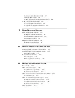
Page 6: ...97 10 USING AUTOMATIC IP CONFIGURATION How Your Switch Obtains IP Information 100 How Automatic IP Configuration Works 100 Automatic Process 101 Important Considerations 102 Server Support 102 Event...

Page 7: ...on Rules for Gigabit Ethernet 123 Configuration Rules for Fast Ethernet 124 Configuration Rules with Full Duplex 125 B NETWORK CONFIGURATION EXAMPLES Simple Network Configuration Examples 128 Segmenta...

Page 8: ...GLOSSARY INDEX...

Page 9: ...g knowledge of local area network LAN operations and familiarity with communication protocols that are used to interconnect LANs For detailed descriptions of the Web interface operations and the Comma...

Page 10: ...mple To change your password use the following syntax system password password In this example you must supply a password for password Commands The word command means that you must enter the command e...

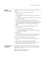
Page 11: ...rStack 3 Switch Management Quick Reference Guide This guide contains a list of the features supported by the Switch a summary of the Web interface and Command Line Interface commands for the Switch Re...

Page 12: ...ntation Guide Part number DUA1720 3BAA04 Page 25 Please note that we can only respond to comments and questions about 3Com product documentation at this e mail address Questions related to technical s...

Page 13: ...sing Resilience Features Chapter 5 Using the Switch Database Chapter 6 Using Traffic Prioritization Chapter 7 Status Monitoring and Statistics Chapter 8 Setting Up Virtual LANs Chapter 9 Using Webcach...

Page 14: ...14...

Page 15: ...ed by the Switch and to change and monitor the way it works you have to access the management software that resides on the Switch This is known as managing the Switch Managing the Switch can help you...

Page 16: ...n encrypted License Key that you must register on the 3Com Web site 2 Visit the following URL on the 3Com Web site http www 3com com register 3 Select Switches 4 Select Switch 4400 SE Enhanced Softwar...

Page 17: ...ing URL http www 3com com register Switch Features Explained The management software provides you with the capability to change the default state of some of the Switch features This section provides a...

Page 18: ...eased As the power is supplied over the Ethernet cable it can be backed up by redundant and uninterruptible power supplies Power Management is only available on the Switch 4400 PWR 3C17205 For more in...

Page 19: ...mode and is implemented using the IEEE Std 802 3 2002 incorporating 802 3x on ports operating in full duplex mode Smart Auto sensing Smart auto sensing allows auto negotiating multi speed ports such a...

Page 20: ...re information about resilient links see Chapter 4 Using Resilience Features Spanning Tree Protocol and Rapid Spanning Tree Protocol Spanning Tree Protocol STP and Rapid Spanning Tree Protocol RSTP ar...

Page 21: ...passes through the Switch for example prioritized or discarded Being able to define exactly how you want your Switch to treat selected applications devices users and types of traffic allows you to ha...

Page 22: ...b pages stored locally on the Webcache this allows your network to operate more efficiently and reduces WAN network traffic To make Webcache support available on the SuperStack 3 Switch 4400 SE upgrad...

Page 23: ...his information if you wish before restoring the configuration If the Switch is part of a stack it is the configuration of the stack that is saved and restored You cannot restore the configuration of...

Page 24: ...tocol enabled Parameters such as VLANs and Fast Start may be set up as required Other combinations of port settings however are not recommended as Configuration Restore will only perform a best effort...

Page 25: ...ation Restore has been completed For detailed descriptions of the Configuration Save and Restore Web interface operations and Command Line Interface CLI commands please refer to the Management Interfa...

Page 26: ...26 CHAPTER 1 SWITCH FEATURES OVERVIEW...

Page 27: ...Features The default state for all the features detailed below provides the best configuration for most users In normal operation you do not need to alter the Switch from its default state However und...

Page 28: ...y determine the best port speed duplex mode only at 10 Mbps and 100 Mbps and flow control When auto negotiation is enabled default a port advertises its maximum capabilities these capabilities are by...

Page 29: ...to the network An SNMP Trap is sent every time a port is down rated to a lower speed Conditions that affect smart auto sensing Smart auto sensing will not operate on links that do not support auto ne...

Page 30: ...dundancy between two devices switch to switch or switch to server that have full duplex connections operating at the same speed By default LACP is disabled on all Switch ports If LACP is enabled on al...

Page 31: ...and managed via network management Implementing 802 3ad Aggregated Links LACP can be enabled or disabled on a per port basis You can implement 802 3ad aggregated links in three ways Manual Aggregation...

Page 32: ...f LACP detects at least two active ports sharing the same partner device and if no matching pre configured aggregated links exist LACP will automatically assign a free un configured aggregated link to...

Page 33: ...nly supports a maximum of four active ports in any individual aggregation Any extra ports will remain in a standby state and may become active if one of the four active ports fails If multiple links a...

Page 34: ...ted pair ports within the same aggregated link The member link ports can have different port configurations within the same aggregated link that is auto negotiation port speed and duplex mode However...

Page 35: ...ggregated link configuration To make this configuration work you need to have two aggregated links defined on Switch A one containing the member links for Switch B and the other containing those for S...

Page 36: ...onfigure the aggregated link at both ends before physically connecting the ports can result in a number of serious network issues such as lost packets and network loops Traffic Distribution and Link F...

Page 37: ...egated link between two Switch units To manually set up this configuration 1 Prepare ports 2 4 6 and 8 on the upper Switch for aggregated links To do this a Check that the ports have an identical conf...

Page 38: ...on the upper Switch to port 2 on the lower Switch 4 Connect port 4 on the upper Switch to port 4 on the lower Switch 5 Connect port 6 on the upper Switch to port 6 on the lower Switch 6 Connect port 8...

Page 39: ...A multicast is a packet that is intended for one to many and many to many communication Users explicitly request to participate in the communication by joining an endstation to a specific multicast g...

Page 40: ...ce QoS There are situations where a multicast approach is more logical and efficient than a unicast approach Application examples include distance learning transmitting stock quotes to brokers and col...

Page 41: ...that wish to join a multicast group and then sets its filters accordingly Query Mode Query mode allows the Switch to function as the Querier if it has the lowest IP address in the subnetwork to which...

Page 42: ...has more than one IP router then the one with the lowest IP address becomes the querier The Switch can be the IGMP querier and will become so if its own IP address is lower than that of any other IGMP...

Page 43: ...bling IGMP multicast learning please refer to the Management Interface Reference Guide supplied on your Switch CD ROM If IGMP multicast learning is not enabled then IP multicast traffic is always forw...

Page 44: ...44 CHAPTER 3 USING MULTICAST FILTERING...

Page 45: ...provide resilience for your network It covers the following topics Resilient Links Spanning Tree Protocol STP Rapid Spanning Tree Protocol RSTP an enhanced version of the STP feature For detailed des...

Page 46: ...those links fail A resilient link is comprised of a resilient link pair containing a main link and a standby link If the main link fails the standby link quickly and automatically takes over the task...

Page 47: ...ave security enabled Neither of the ports have network login enabled Neither of the ports are part of an aggregated link Neither of the ports belong to another resilient link pair The port state of po...

Page 48: ...onds RSTP or STP will detect any misconfiguration that may cause a temporary loop and react accordingly If you have Fast Start disabled on a port the Switch will wait for 30 seconds before RSTP or STP...

Page 49: ...creates loops that cause the network to overload Figure 9 A network configuration that creates loops Figure 10 shows the result of enabling STP on the bridges in the configuration STP detects the dupl...

Page 50: ...P re evaluated the situation and opened the path through Bridge B How STP Works When enabled STP determines the most appropriate path for traffic through a network It does this as outlined in the sect...

Page 51: ...t Note that the Root Bridge does not have a Root Port The identity of the bridge that is to be the Designated Bridge of each LAN segment The Designated Bridge is the one that has the lowest Root Path...

Page 52: ...SNMP trap destination when the topology of your network changes the first bridge to detect the change sends out an SNMP trap CAUTION Network loops can occur if aggregated links are manually configured...

Page 53: ...elected as the Designated Bridge Port for LAN Segment 1 Port 1 of Bridges B C X and Y have been defined as Root Ports because they are the nearest to the Root Bridge and therefore have the most effici...

Page 54: ...s both have STP enabled and are connected by two links STP discovers a duplicate path and blocks one of the links If the enabled link breaks the disabled link becomes re enabled therefore maintaining...

Page 55: ...How STP Works 55 Figure 13 STP configurations...

Page 56: ...ersion 2 0 default settings including RSTP enabled If you connect a new Switch with version 2 0 already loaded to a stack of upgraded units all the upgraded units will assume the default settings of t...

Page 57: ...ed using the 802 1Q tagged link between Switch B and Switch C By default this link has a path cost of 100 and is automatically blocked because the other Switch to Switch connections have a path cost o...

Page 58: ...58 CHAPTER 4 USING RESILIENCE FEATURES...

Page 59: ...Started Guide that accompanies your Switch For detailed descriptions of the Web interface operations and the Command Line Interface CLI commands that you require to manage the Switch please refer to...

Page 60: ...ion is removed from the network its entry is also removed from the database Learned entries are removed from the Switch Database if the Switch is reset or powered down Non aging learned If the aging t...

Page 61: ...pplications devices users and types of traffic allows you to have more control over your network There are two different categories of rules Application based rules describe how to deal with traffic f...

Page 62: ...e for the same bandwidth a network can quickly become overloaded resulting in slow response times long latency and application time outs Traffic prioritization is a mechanism that allows you to priori...

Page 63: ...ts priority level for onward transmission across the network or The level of service configured at the Switch for incoming traffic the network administrator configures the Switch to prioritize or disc...

Page 64: ...affic The Switch employs several methods of classifying identifying traffic These can be based on any combination of fields in the first 64 bytes of the packet and at different levels of the OSI 7 lay...

Page 65: ...follows the destination MAC address and Source MAC address The IEEE Std 802 1D 1998 Edition priority marking scheme assigns each frame with an IEEE 802 1p priority level between 0 and 7 which determin...

Page 66: ...iated Services DiffServ Traffic Marking DiffServ is a Layer 3 marking scheme that uses the DiffServ Code Point DSCP field in the IP header to store the packet priority information DSCP is an advanced...

Page 67: ...he rules set up by the network administrator Basic Traffic Prioritization Incoming traffic is classified based upon the IEEE 802 1D frame and is assigned to the appropriate priority queue based upon t...

Page 68: ...o traffic queue in the Switch is proprietary and is slightly different to the recommended IEEE mapping Figure 15 IEEE 802 1p priority levels and recommended IEEE 802 1D traffic types The number of que...

Page 69: ...the current applications for example Microsoft Word Lotus Notes and NetMeeting are not QoS aware and do not apply a service level to the traffic that they send Being an intelligent Switch your Switch...

Page 70: ...et 4 Remarking the 802 1p tag DSCP field or dropping the packet are optional and have to be configured by the network administrator 5 It is the priority associated with the packet that is used to dire...

Page 71: ...edence over low priority but in the event that high priority traffic exceeds the link capacity lower priority traffic is not blocked Traffic queues cannot be enabled on a per port basis on the Switch...

Page 72: ...e stack the QoS configuration defined in the profile will immediately become active Methods of Configuring Traffic Prioritization QoS can be configured on your Switch using 3Com Network Supervisor or...

Page 73: ...recommended configuration for most networks is 10 100 Mbps switching to the desktop Gigabit connections for servers and non blocking Gigabit backbones QoS requires the support of every network device...

Page 74: ...th IP TOS based networks Default QoS Configurations The Switch has some pre configured defaults which are listed in Table 7 and Table 8 Table 7 Default traffic classifiers configured in your Switch Ta...

Page 75: ...itch port Figure 17 University campus QoS network example See Utilizing the Traffic Prioritization Features of Your Network on page 133 for a further network example Some examples of rules that can be...

Page 76: ...an_ph one pdf correct at time of publication For additional troubleshooting information and technical solutions visit the 3Com Knowledgebase The Knowledgebase has solutions addressing the blocking of...

Page 77: ...it to monitor the traffic of other ports on the Switch The system works by enabling you to define an analysis port the port that is connected to the analyzer and a monitor port the port that is to be...

Page 78: ...s statistics about a LAN segment or VLAN and transfers the information to a management workstation on request or when a pre defined threshold is crossed The workstation does not have to be on the same...

Page 79: ...shold and falling threshold Effective use of the Events group saves you time rather than having to watch real time graphs for important occurrences you can depend on the Event group for notification T...

Page 80: ...ics No Statistics sessions per VLAN supported on Switch 4400 other than VLAN 1 A new or initialized Switch has one Statistics session per port and one default Statistics session for VLAN 1 History No...

Page 81: ...ed in Table 11 The Default Alarm Settings A new or initialized Switch has the following alarm defined for each port Number of errors over 10 seconds The default values and actions for this alarm is gi...

Page 82: ...ur You can receive notification via email SMS Short Message Service or pager of the event that has occurred This feature uses an SMTP Simple Mail Transfer Protocol email client to send the notificatio...

Page 83: ...aps continue to be sent in addition to any email notifications you may receive The events that can generate email notification are Unit powers up Fan in the unit fails Unit in the stack fails A link f...

Page 84: ...84 CHAPTER 7 STATUS MONITORING AND STATISTICS...

Page 85: ...Guide supplied in HTML format on the CD ROM that accompanies your Switch What are VLANs A VLAN is a flexible group of devices that can be located anywhere in a network but which communicate as if the...

Page 86: ...st be updated manually With a VLAN setup if an endstation in VLAN Marketing for example is moved to a port in another part of the network and retains its original subnet membership you only need to sp...

Page 87: ...lowing information about each VLAN on your Switch before the Switch can use it to forward traffic VLAN Name This is a descriptive name for the VLAN for example Marketing or Management 802 1Q VLAN ID T...

Page 88: ...if a port is in a single VLAN it can be an untagged member but if the port needs to be a member of multiple VLANs tagged membership must be defined Typically endstations for example clients will be un...

Page 89: ...switch In this network there is no requirement to pass traffic for multiple VLANs across a link All traffic is handled by the single Switch and therefore untagged connections can be used The example...

Page 90: ...use 802 1Q tagged connections so that all VLAN traffic can be passed along the links between the Switches 802 1Q tagging can only be used if the devices at both ends of a link support IEEE 802 1Q The...

Page 91: ...e VLANs on Switch 2 Define VLAN 2 VLAN 1 is the default VLAN and already exists 5 Add endstation ports on Switch 2 to the VLANs Place the endstation ports in the appropriate VLANs as untagged members...

Page 92: ...92 CHAPTER 8 SETTING UP VIRTUAL LANS...

Page 93: ...is Webcache Support Webcache support is a feature that allows local storage caching of frequently accessed web pages on a Webcache attached to your network This means your network users can access the...

Page 94: ...ple units are configured in this way then the master unit will select the first unit that responds to be the polling unit The polling unit polls for the Webcache using the Webcache health check URL se...

Page 95: ...health check works as follows 1 The health check requests a factory defined URL from the Webcache every eleven seconds and expects to receive a reply to confirm that the cache is operating normally 2...

Page 96: ...follows 1 A PC sends a request for a web page in the form of HTTP traffic 2 The Switch receives the request from the PC it detects that the traffic is HTTP and redirects it to the Webcache instead of...

Page 97: ...ck On the Switch 4400 the Webcache must reside on VLAN1 The SuperStack 3 Webcache 1000 3000 can only receive untagged packets therefore it must be connected to an untagged port on the Switch 4400 The...

Page 98: ...98 CHAPTER 9 USING WEBCACHE SUPPORT...

Page 99: ...For detailed information on setting up your Switch for management see the Getting Started Guide that accompanies your Switch For detailed descriptions of the Web interface operations and the Command...

Page 100: ...c configuration methods The Switch tries each method in a specified order Manual IP Configuration you can manually input the IP information IP address subnet mask and default gateway If you select an...

Page 101: ...col ARP to check to make sure this address is not already in use on the network If not it will allocate this default address to the Switch If this IP address is already in use Auto IP will check once...

Page 102: ...ystems Microsoft Windows 2000 Server Microsoft Windows NT4 Server Sun Solaris v2 5 1 If you want DHCP or BOOTP to be the method for automatic configuration make sure that your DHCP or BOOTP servers ar...

Page 103: ...se features and gives examples of how and why you would use them in your network For detailed descriptions of the Web interface operations and the Command Line Interface CLI commands that you require...

Page 104: ...nformation see What is Disconnect Unauthorized Device DUD on page 107 Network Login When the user has been successfully authorized all network traffic is forwarded through the port without any restric...

Page 105: ...e client device is granted access to the network For further information about RADIUS see What is RADIUS on page 112 The client device must be directly connected to the Switch port no intervening swit...

Page 106: ...s shown in Figure 23 The Switch does not interpret or store this information Figure 23 Network Login Operation When the client device and RADIUS server have exchanged authentication information the Sw...

Page 107: ...port may not support the authentication service for example printers You should configure the Switch port to operate in Automatic Learning mode so that network traffic that does not match the MAC add...

Page 108: ...Login If you intend to manage the Switch using the Web interface or the Command Line Interface you need to log in with a valid user name and password For further information on managing the Switch se...

Page 109: ...n bad configurations and lapses in security RADIUS authentication provides centralized secure access and removes the need to physically visit each network device Changes to user names and passwords re...

Page 110: ...cify the access level required for each user account The configurable attribute values are Monitor 1 the user can view all manageable parameters except special security features but cannot change any...

Page 111: ...thentication Vendor Specific Attribute VSA The Vendor ID for 3Com is 43 If the Switch is unable to contact the RADIUS server the Command Line Interface automatically reverts to using the local Switch...

Page 112: ...ransactions between each network device and the server are authenticated by the use of a shared secret Additional security is provided by encryption of passwords to prevent interception by a network s...

Page 113: ...ly the power required by the device providing that the total power budget for the Switch would not be exceeded by doing so Benefits of Power over Ethernet A Power over Ethernet Switch combines the fun...

Page 114: ...ower delivered does not exceed 150 watts When you plan your network you need to calculate the maximum power that you will need and make sure that the Switch is not expected to supply more than its max...

Page 115: ...is is the case you may choose to Add additional Power over Ethernet switches This will enable to you guarantee power to each port on the Switch that supplies a Power over Ethernet device The remaining...

Page 116: ...thernet device To ensure that the Switch is able to supply power to each device for which it has guaranteed power the Switch reserves the maximum power that each guaranteed device can draw regardless...

Page 117: ...hernet information See Introducing the Superstack 3 Switch 4400 in the Getting Started Guide There is a Power over Ethernet fault Push the LED Mode button to change to power mode and see the details o...

Page 118: ...wer that has been supplied to the device since the meter was last reset If a device had been switched off for part of the time it will register a lower average Peak Power displays the most power suppl...

Page 119: ...the port is active The height of the bar shows the level of power being drawn Gray if the port has been disabled Red if there is a Power over Ethernet fault on the port Problem Solving If a device is...

Page 120: ...120 CHAPTER 12 POWER MANAGEMENT AND CONTROL...

Page 121: ...II APPENDICES AND INDEX Appendix A Configuration Rules Appendix B Network Configuration Examples Appendix C IP Addressing Glossary Index...

Page 122: ...122...

Page 123: ...1804 ft Category 5 cabling with connections up to 100 m 328 ft The different types of Gigabit Ethernet media and their specifications are detailed in Table 15 Table 15 Gigabit Ethernet cabling Gigabit...

Page 124: ...re 26 illustrates the key topology rules and provides examples of how they allow for large scale Fast Ethernet networks Figure 26 Fast Ethernet configuration rules The key topology rules are Maximum U...

Page 125: ...to the endstations Configuration Rules with Full Duplex The Switch provides full duplex support for all its ports including Expansion Module ports Full duplex allows packets to be transmitted and rece...

Page 126: ...126 APPENDIX A CONFIGURATION RULES...

Page 127: ...Configuration Examples Segmentation Switch Example Collapsed Backbone Switch Example Desktop Switch Example Advanced Network Configuration Examples Improving the Resilience of Your Network Enhancing t...

Page 128: ...n be used in your network Segmentation Switch Example The example in Figure 27 shows how a 10 100 Switch such as the Switch 4400 stack can segment a network of shared 10 Mbps and 100 Mbps connections...

Page 129: ...n Examples 129 Collapsed Backbone Switch Example The example in Figure 28 shows how a Switch 4400 stack can act as a backbone for both shared and switched network segments Figure 28 Using the Switch 4...

Page 130: ...witch 4400 can be used for a group of users that require dedicated 10 Mbps or 100 Mbps connections to the desktop The Switch 4400 stack has a 1000BASE T Module fitted that allows it to provide a Gigab...

Page 131: ...itch Improving the Resilience of Your Network Figure 30 shows how you can set up your network to improve its resilience using resilient links Alternatively instead of setting up resilient links you ca...

Page 132: ...auto sensing and will therefore pass data across the network at the optimum available speed and duplex mode Flow control will help avoid packet loss during periods of network congestion A Gigabit Eth...

Page 133: ...uration that demonstrates how you can utilize the different types of Quality of Service QoS profiles to ensure a high level of service and prioritization across the network for certain applications us...

Page 134: ...134 APPENDIX B NETWORK CONFIGURATION EXAMPLES...

Page 135: ...ress is Advanced Overview Gives a more in depth explanation of IP addresses and the way they are structured Simple Overview To operate correctly each device on your network must have a unique IP addre...

Page 136: ...Registration Services is the organization responsible for supplying registered IP addresses The following contact information is correct at time of publication World Wide Web site http www internic ne...

Page 137: ...lasses of IP addresses are as follows Class A address Uses 8 bits for the network part and 24 bits for the host part Although only a few Class A networks can be created each can contain a very large n...

Page 138: ...s a subnetwork part a subnet mask identifies the bits that constitute the subnetwork address and the bits that constitute the host address A subnet mask is a 32 bit number in the IP address format The...

Page 139: ...The number that includes both the Class B natural network mask 255 255 and the subnet mask 255 240 is sometimes called the extended network prefix Continuing with the previous example the subnetwork...

Page 140: ...ments When it receives the IP packets the gateway determines the next network hop on the path to the remote destination and sends the packets to that hop This could either be the remote destination or...

Page 141: ...thernet over fiber optic cable 802 11af The IEEE specification for Power over Ethernet See Power over Ethernet aging The automatic removal of dynamic entries from the Switch Database which have timed...

Page 142: ...packet sent to all devices on a network broadcast storm Multiple simultaneous broadcasts that typically absorb all the available network bandwidth and can cause a network to fail Broadcast storms can...

Page 143: ...ion using a networking device Forwarding Database See Switch Database filtering The process of screening a packet for certain characteristics such as source address destination address or protocol Fil...

Page 144: ...relevant sections of the IEEE Std 802 1D 1998 Edition IEEE Std 802 1Q 1998 A standard that defines VLAN tagging IEEE Std 802 3ad A standard that defines link aggregation 802 3ad is now incorporated in...

Page 145: ...rnetwork Packet Exchange IPX is a layer 3 and 4 network protocol designed for networks that use Novell Netware IP address Internet Protocol address A unique identifier for a device attached to a netwo...

Page 146: ...he receiver of another device MDI X Medium Dependent Interface Cross over An Ethernet port connection where the internal transmit and receive lines are crossed MIB Management Information Base A collec...

Page 147: ...r of ports that can be configured so that one takes over data transmission should the other fail See also main port and standby port RMON IETF Remote Monitoring MIB A MIB that allows you to remotely m...

Page 148: ...a single logical device standby port The port in a resilient link that takes over data transmission if the main port in the link fails STP See Spanning Tree Protocol STP subnet mask A subnet mask is...

Page 149: ...he local management capabilities of the Switch traffic prioritization A system which allows data that has been assigned a high priority to be forwarded through a switch without being obstructed by oth...

Page 150: ...150 GLOSSARY...
Page 151: ...art 56 RSTP 56 default gateway 140 Default VLAN 87 Designated Bridge 51 Designated Bridge Port 52 DHCP 100 Disconnect Unauthorized Device DUD 18 107 E event notification 22 82 Events RMON group 79 80...

Page 152: ...6 power budgets 114 power LEDs 117 power management 18 Power over Ethernet 113 advantages 113 power plan 116 power usage 116 monitoring 118 priority in STP 50 Q QoS see Quality of Service 21 61 Qualit...

Page 153: ...gy rules for Fast Ethernet 124 topology rules with full duplex 125 traffic prioritization 21 61 62 advanced 69 basic 67 classification 64 default configurations 74 differentiated services 65 66 DiffSe...

Reviews: