


8
By inserting
δ
=
Λ
/
T
d
,
ω
0
= 2
π
/
T
0
and
ω
d
= 2
π
/
T
d
into the equation
ω
ω
δ
d
0
2
2
=
−
we obtain:
T
T
d
0
2
2
= ⋅ +
1
4
Λ
π
whereby the period T
d
can be calculated precisely pro-
vided that T
0
is known.
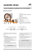
3.4 Forced oscillations
In the case of forced oscillations a rotating motion with
sinusoidally varying torque is externally applied to the
system. This exciter torque can be incorporated into
the motion equation as follows:
J
b
D
M
t
⋅ + ⋅ + ⋅ =
⋅
⋅
(
)
ϕ
ϕ
ϕ
ω
..
.
sin
E
E
After a transient or settling period the torsion pendu-
lum oscillates in a steady state with the same angular
frequency as the exciter, at the same time
ω
E
can still
be phase displaced with respect to
ω
0
.
Ψ
0S
is the sys-
tem’s zero-phase angle, the phase displacement be-
tween the oscillating system and the exciter.
ϕ
=
ϕ
S
· sin (
ω
E
·
t
–
Ψ
0S
)
The following holds true for the system amplitude
ϕ
S
ϕ
ω
ω
δ ω
=
−
(
) +
⋅
M
J
E
0
2
E
2
2
E
2
4
2
The following holds true for the ratio of system ampli-
tude to the exciter amplitude
ϕ
ϕ
ω
ω
δ
ω
ω
ω
S
E
E
E
0
2
2
0
2
E
0
2
=
−
+
⋅
M
J
1
4
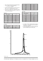
In the case of undamped oscillations, theoretically
speaking the amplitude for resonance (
ω
E
equal to
ω
0
)
increases infinitely and can lead to “catastrophic reso-
nance”.
In the case of damped oscillations with light damping
the system amplitude reaches a maximum where the
exciter’s angular frequency
ω
E res
is lower than the sys-
tem’s natural frequency. This frequency is given by
ω
ω
δ
ω
Eres
0
2
0
2
=
⋅ −
1
2
Stronger damping does not result in excessive ampli-
tude.
For the system’s zero phase angle
Ψ
0S
the following is
true:
Ψ
0S
0
2
2
=
−
arctan
2
δ ω
ω
ω
ω
For
ω
E
=
ω
0
(resonance case) the system’s zero-phase
angle is
Ψ
0S
= 90°. This is also true for
δ
= 0 and the
oscillation passes its limit at this value.
In the case of damped oscillations (
δ
> 0) where
ω
E
<
ω
0
, we find that 0°
≤
Ψ
0S
≤
90° and when
ω
E
>
ω
0
it is found that 90°
≤
Ψ
0S
≤
180°.
In the case of undamped oscillations (
δ
= 0),
Ψ
0S
= 0°
for
ω
E
<
ω
0
and
Ψ
0S
= 180° for
ω
E
>
ω
0
.
4. Operation
4.1 Free damped rotary oscillations
•
Connect the eddy current brake to the variable volt-
age output of the DC power supply for torsion pen-
dulum.
•
Connect the ammeter into the circuit.
•
Determine the damping constant as a function of
the current.
4.2 Forced oscillations
•
Connect the fixed voltage output of the DC power
supply for the torsion pendulum to the sockets (16)
of the exciter motor.
•
Connect the voltmeter to the sockets (15) of the
exciter motor.
•
Determine the oscillation amplitude as a function
of the exciter frequency and of the supply voltage.
•
If needed connect the eddy current brake to the
variable voltage output of the DC power supply for
the torsion pendulum.
4.3 Chaotic oscillations
•
To generate chaotic oscillations there are 4 supple-
mentary weights at your disposal which alter the
torsion pendulum’s linear restoring torque.
•
To do this screw the supplementary weight to the
body of the pendulum (5).