


7
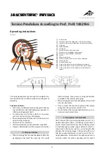
unwinds the coil spring then compresses it again in a
periodic sequence and thereby initiates the oscillation
of
the
copper
wheel.
The
electromagnetic
eddy
cur-
rent
brake
(11)
is
used
for
damping.
A
scale
ring
(4)
with slots and a scale in 2-mm divisions extends over
the
outside
of
the
oscillating
system;
indicators
are
located on the exciter and resonator.
The device can also be used in shadow projection dem-
onstrations.
Natural frequency: 0.5 Hz approx.
0 to 1.3 Hz (continuously adjust-
Exciter frequency:
able)
Terminals:
Motor:
max. 24 V DC, 0.7 A,
via 4-mm safety sockets
Eddy current brake:
0 to 20 V DC, max. 2 A,
via 4-mm safety sockets
Scale ring:
300 mm Ø
400 mm x 140
Dimensions:
mm x 270 mm
4 kg
Ground:
2.1 Scope of supply
1 Torsional pendulum
2 Additional 10 g weights
2 Additional 20 g weights
3. Theoretical Fundamentals
3.1 Symbols used in the equations
Angular directional variable
D
=
Mass moment of inertia
=
J
Restoring torque
=
M
Period
=
T
T
0
Period of an undamped system
=
T
d
Period of the damped system
=
M
E
Amplitude of the exciter moment
=
Damping torque
=
b
Frequency
=
n
Time
=
t
Λ
Logarithmic decrement
=
δ
Damping constant
=
ϕ
Angle of deflection
=
ϕ
0
Amplitude at time t = 0 s
=
ϕ
n
Amplitude after n periods
=
ϕ
E
Exciter amplitude
=
ϕ
S
System amplitude
=
ω
0
Natural frequency of the oscillating system
=
ω
d
Natural frequency of the damped system
=
ω
E
Exciter angular frequency
=
ω
E
res
Exciter angular frequency for max. amplitude
=
Ψ
0S
System zero phase angle
=
3.2 Harmonic rotary oscillation
A harmonic oscillation is produced when the restoring
torque is proportional to the deflection. In the case of
harmonic rotary oscillations the restoring torque is
proportional to the deflection angle
ϕ
:
M = D ·
ϕ
The coefficient of proportionality D (angular direction
variable) can be computed by measuring the deflec-
tion angle and the deflection moment.
If the period duration T is measured, the natural reso-
nant frequency of the system
ω
0
is given by
ω
0
= 2
π
/T
and the mass moment of inertia J is given by
ω
0
2
=
D
J
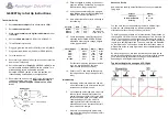
3.3 Free damped rotary oscillations
An oscillating system that suffers energy loss due to
friction, without the loss of energy being compensated
for by any additional external source, experiences a
constant drop in amplitude, i.e. the oscillation is
damped.
At the same time the damping torque b is proportional
to the deflectional angle
ϕ
.
.
The following motion equation is obtained for the
torque at equilibrium
J
b
D
⋅ + ⋅ + ⋅ =
ϕ
ϕ
ϕ
..
.
0
b = 0 for undamped oscillation.
If the oscillation begins with maximum amplitude
ϕ
0
at t = 0 s the resulting solution to the differential equa-
tion for light damping (
δ
² <
ω
0
²) (oscillation) is as fol-
lows
ϕ
=
ϕ
0
·
e
–
δ
·t
· cos (
ω
d
·
t
)
δ
= b/2 J is the damping constant and
ω
ω
δ
d
0
2
2
=
−
the natural frequency of the damped system.
Under heavy damping (
δ
² >
ω
0
²) the system does not
oscillate but moves directly into a state of rest or equi-
librium (non-oscillating case).
The period duration T
d
of the lightly damped oscillat-
ing system varies only slightly from T
0
of the undamped
oscillating system if the damping is not excessive.
By inserting
t
=
n
·
T
d
into the equation
ϕ
=
ϕ
0
·
e
–
δ
·t
· cos (
ω
d
·
t
)
and
ϕ
=
ϕ
n
for the amplitude after n periods we ob-
tain the following with the relationship
ω
d
= 2
π
/
T
d
ϕ
ϕ
δ
n
0
d
=
⋅
− ⋅
e
T
n
and thus from this the logarithmic decrement
Λ
:
Λ = ⋅ = ⋅
=
δ
ϕ
ϕ
ϕ
ϕ
T
n
In
In
d
n
0
n
n+1
1