Copyright 2Touch Technologies Limited 2007-2008. All rights reserved.
3.
Connect the board to your computer. Using USBSettings software,
check the camera traces. Work around the board, observing camera
outputs, and ensure that board is level and flat while applying the
remaining screws to secure the board to the brackets at each corner.
Secure top & bottom edges of board with total five screws (ie three
additional) each edge.
Configuring the 2Touch Board to suit multiple platforms
By default, every 2Touch board is pre-configured for optimum performance
using Windows 7. Where a site needs cross-platform support or needs to
support a different platform such as Apple Macintosh or Linux, the installer
will need to change the default configuration of the board to permit this.
Under the mouse tab in the USB Config utility, select “on” the “Mac
compatibility” field. This will revert the board to support multiple platforms on
a plug-and-play (ie no additional drivers) basis, however it will limit the board
from supporting the standard multi-touch functions under Windows 7.
Installing the 2Touch USB Hub
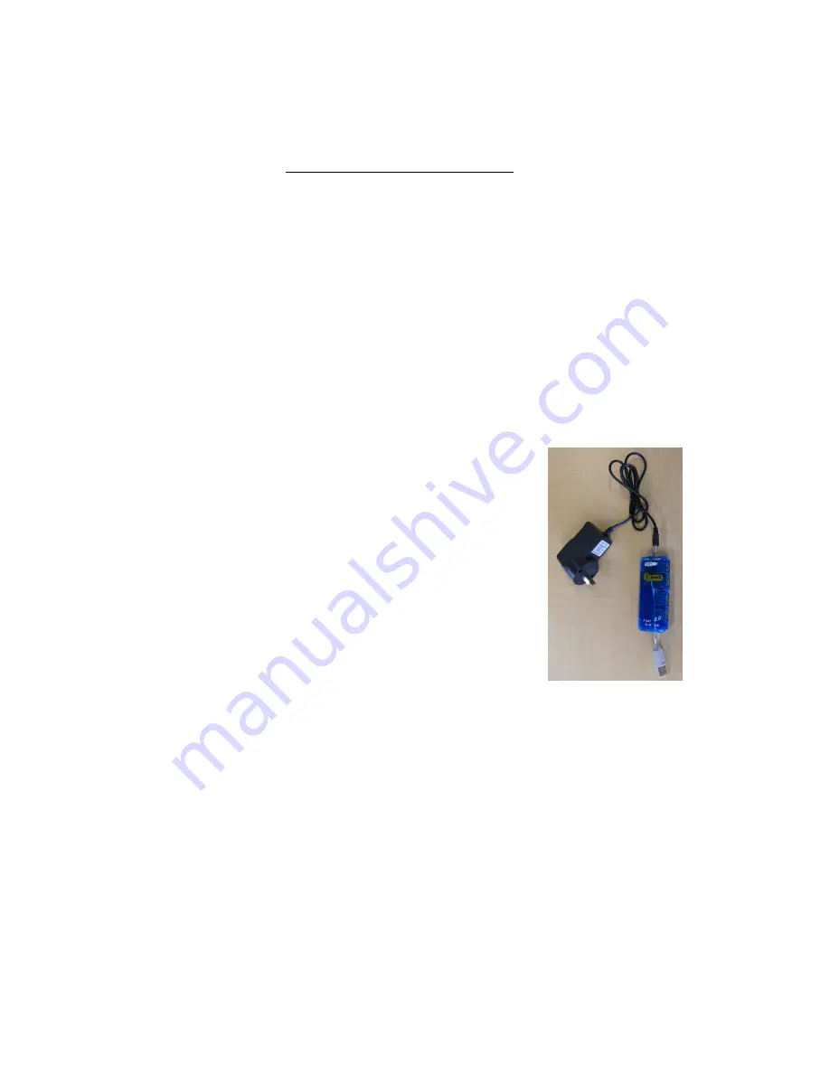
A four-port USB 2.0 powered hub is available for use
with 2Touch IWB’s. This unit and its power supply have
been extensively tested for compatibility.
1.
The USB hub may be placed within cavity at base
of speaker model 014 (if applicable) by using a
right angle power connector (not supplied).
Otherwise, place the USB hub behind the edge of
board in such a position that it may be accessed
later if required.
2.
Power connection to USB hub is required.
Optimally, a GPO can be placed behind the board
to furnish this provided that sufficient gap is available between the
board and the wall to accommodate the thickness of the supplied
power pack (50mm). Otherwise, a GPO will need to be provided within
900mm of the hub.
3.
USB connection to IWB: The USB flylead on the 2Touch IWB is 1.6m
long with a type A plug, and emerges from a position 300mm from the
top left corner of the IWB. This flylead will reach a hub placed
anywhere on the left edge of the IWB; however a 2m USB extension
cable will be required to reach a hub position on the right edge of the
IWB.
4.
USB connection toward computer: Depending on the placement of the
hub, and on the wall panel location, an additional USB type A male –
type A female extension may be required to run from the hub to the
wall panel location.


