


23
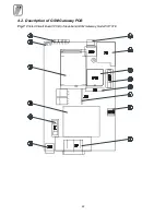
Explanatory Notes
1. LED indicators
2. TL1 - Reset pushbutton
3. SIEMENS
®
GSM module TC35
4. Mains transformer
5. P1 - Mains fuse – T 200 m A
6. X6 – telephone line RJ-12 connector
7. X7 – mains supply connector
8. U16 – EEPROM containing GSM Gateway programmed parameters
9. JP1 - diagnostic connector of power part
10. X8 - diagnostic connector of digital part
11. U15 – auxiliary micro controller in the socket
12. U10 – main micro controller in the socket
13. X9 – SIM card holder
14. Antenna connector
Notes:
•
The main microcontroller can be removed with a specialized tool only. Using another tool
may cause damage to or destroy the PCB!
•
The main microcontroller contains a serial number of GSM gateway and a program code.
Only the manufacturer can upgrade it.
4.3. Fuse Exchange
•
Fuse for AC power can be replaced only by service which is able to check such parameters
as power consumption, DC voltages etc.
•
Use only a fuse of the same value and type.
•
Disconnect the AC power cable while replacing fuse.
•
If a fuse fails again, manufacturer must repair equipment.
Summary of Contents for ATEUS 501101E
Page 2: ......
Page 35: ...33 5 4 11 Remote Supervision Establishing Flow Chart ...
Page 56: ......
Page 57: ... 2002 2N TELEKOMUNIKACE a s Prague DR 972 v 1 33 ...