

11
11.
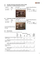
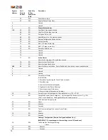
Examples of CT Range and Setup for Starter Panels
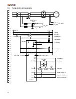
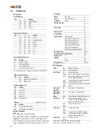
11.1
22kW Starter for 8kW & 20kW Flygt Pumps (1kV)
Pump Model
Rated
Current
Flygt 8kW 2125
6.2 A
Flygt 20kW 2151
14A
CT Set to 20A
CT is Dwyer CCT40 with selectable
ranges of 10A, 20A, 50A. Set to 20A.
Set Current Range DIP Switches to
100%
Current Range
SW
1
2
Setting
Off
Off
100% (default)
11.2
37kW Starter for 20kW & 37kW Flygt Pumps (1kV)
Pump Model
Rated
Current
Flygt 20kW 2151
14A
Flygt 37kW 2201
26 A
To use with an 8kW & 20kW Pumps it
would be best to set the CT to Mid
(20A) Range.
CT Set to 50A
CT is Dwyer CCT40 with selectable
ranges of 10A, 20A, 50A. Set to 50A.
Set Current Range DIP Switches to
100%
Current Range
SW
1
2
Setting
Off
Off
100% (default)
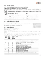
11.3
Other Options
You can scale the current measurements in a few different ways
R
ated C
u
rr
e
n
t
(F
LC
) A
mp
s
C
T R
ati
n
g
A
mp
s
SC10 Current Range
A
t Ra
te
d
C
u
rr
e
n
t S
C
10
wi
ll D
ispl
ay
R
an
ge
DIP Switches
SW 1
SW 2
An Example: Optimal setup for an 8kW Pump. (Based on 11.1 above.)
Option 1: As above.
8
6
20
100%
off
off
30%
30% of the range really is a bit low. It would be best to adjust the range to increase the measurement.
Option 2: Change the
Range Setting on the
SC10
8
6
20
50%
off
on
60%
This gives a range of 10A and at FLC this shows 60%. (If you mount the SC10 so that its front panel is accessible
then this change could be done safely without opening the starter panel.)
Option 3: Change the
Range setting on the CT
to 10A.
8
6
10
100%
off
off
60%
Results are the same as option 2. (This requires disconnection of power and adjustment by an electrician inside
the starter panel.)
Option 4: Put another
turn through the CT
8
6
10
100%
off
off
60%
Results are the same as options 2 & 3, but this requires an electrician to change the wiring.


