14
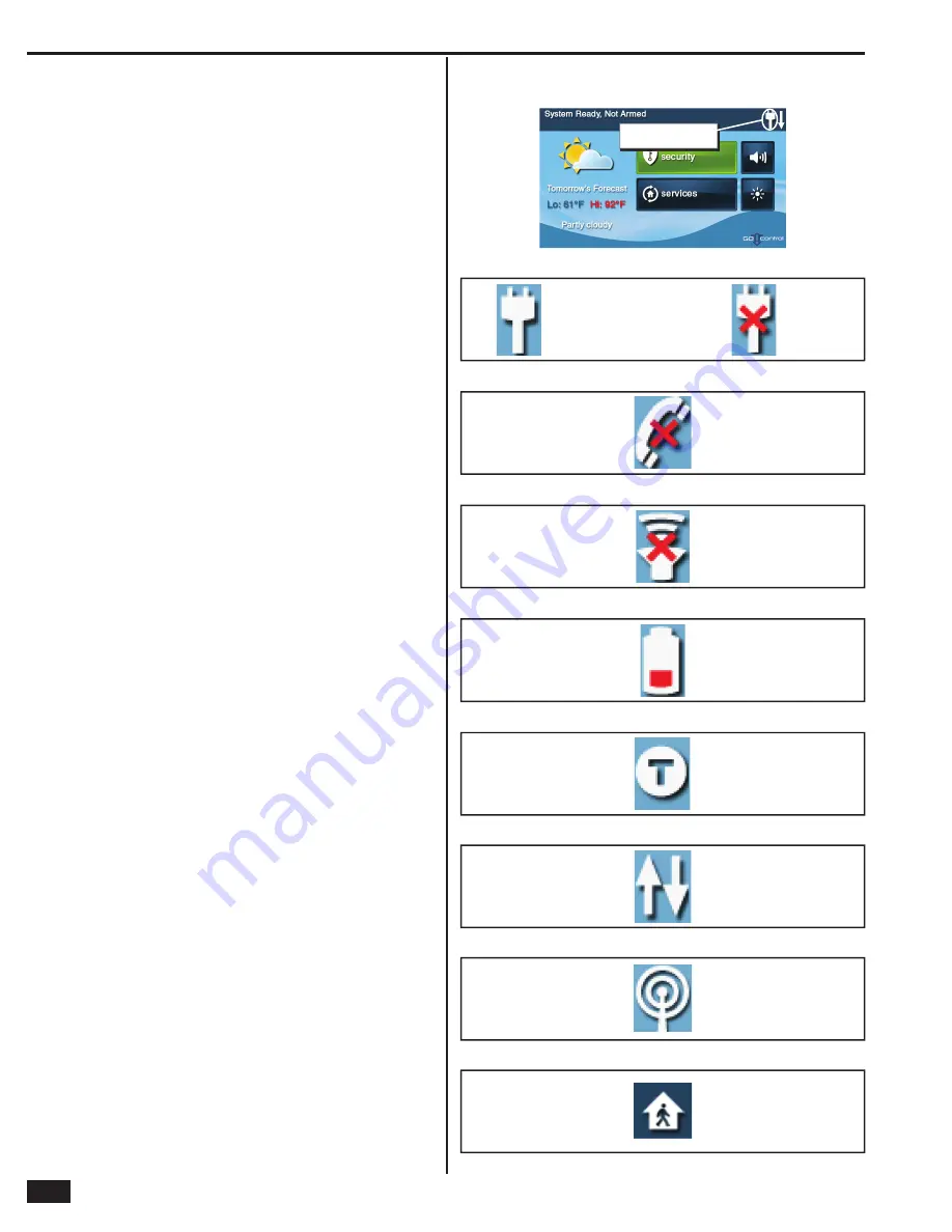
System Status Icons
The top line of the Control Panel’s display is the status bar that
shows the current system mode, the status of the sensors, and
any current system trouble alerts. Special icons are displayed to
visually show the system’s current condition.
AC Power Icon
The AC power icon indicates the Control Panel’s AC line power
status. The icon displays a white plug when the AC power is
present; the icon will display with a red “X” over the white plug
when AC power is absent.
Phone Line Failure Icon
If the Control Panel detects that the telephone line is disconnected,
the phone line failure icon will be displayed.
Sounder Disable Icon
If the system’s internal sounder has been lowered and external
sounder has been disabled by the installer for testing, the sounder
disable icon will be displayed. Also fl ashes to indicate silent arming.
Backup Battery Status Icon
If the Control Panel’s backup battery tests low, the low backup
battery icon will be displayed.
Test Mode Icon
When the system is being tested in Walk Test Mode, the test mode
icon will be displayed on the status bar.
Touch Screen Keypad Traffi c Icon
When the Control Panel is communicating to a touch screen
keypad the up arrow icon is displayed. When a touch screen
keypad communicates to the Control Panel the down arrow icon
is displayed.
GSM Radio Icon
If the system’s optional GSM radio modem is installed, the GSM
radio icon will be displayed while the Control Panel is receiving
over-the-air fi rmware updates.
Interior Sensor Open Icon
If an interior sensor is open (or a motion detector has just been
activated) the house icon will be displayed on the status bar. As a
warning, the icon fl ashes during arming.
Figure 31. System Status Bar
STATUS
B
AR SHOWIN
G
AC POWER IS ON
Figure 32. AC Power Icons
AC POWER ON
AC POWER OFF
Figure 33. Phone Line Failure Icon
PHONE LINE
FAILURE
Figure 34. Sounder Disable Icon
SOUNDER
DISA
B
LED
Figure 35. Backup Battery Status Icon
LOW
B
ACKUP
B
ATTERY
Figure 36. Test Mode Icon
SYSTEM IN
TEST MODE
Figure 37. Touch Screen Keypad Traffi c Icon
COMMUNICATION
IN PROCESS
Figure 38. GSM Radio Icon
OVER-THE-AIR
UPDATE IN
PROCESS
Figure 39. Interior Sensor Open Icon
INTERIOR
SENSOR OPEN
Summary of Contents for GO!control 2GIG-CNTRL2
Page 1: ...Wireless Security System Installation Programming Instructions 2GIG CNTRL2 2GIG CP2...
Page 48: ...46 Notes...
Page 49: ...47 Notes...
Page 52: ...v1 9 233497 E Copyright 2012...


