


11
Installation
HAN
G
CON
S
OLE
ON
S
T
R
AP
1
2
CONNECT HA
R
DWI
R
E LOOP
S
,
EXTE
R
NAL
S
OUNDE
R
, AND
OPEN COLLECTO
R
OUTPUT
TO TE
R
MINAL
S
3
PLU
G
TELEPHONE LINE
INTO TELEPHONE JACK
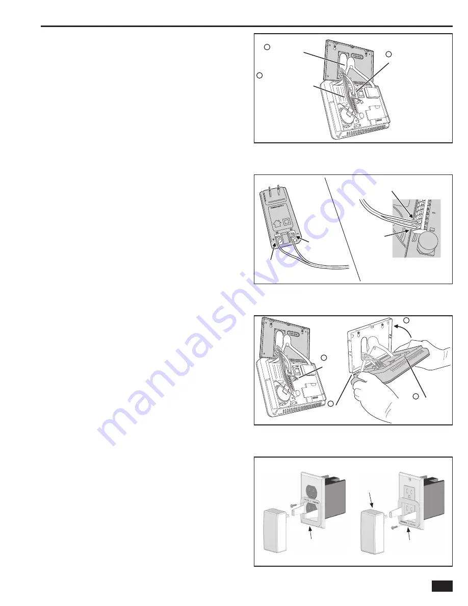
Figure 16. Control Panel Mounting
Control Panel Wiring
The Control Panel includes a “third hand” plastic strap that allows
the unit to hang on the mounting plate during installation.
1.
Hang the Control Panel on the mounting plate using
the “third hand” strap (see Figure 16).
2.
Connect the hardwire loop, external sounder, and open collector
output wiring (if used ) to the Control Panel’s terminal block.
3.
Plug the telephone line (if used ) into the connector
on the Control Panel’s circuit board.
Backup Battery Connection and Power Supply Wiring
The backup battery connects to the Control Panel’s circuit board
with a two-pin header assembly.
The power supply features a two-position terminal block for
connecting the power supply to the Control Panel power terminals
(connection wire not included).
1.
Determine a good location where there’s a 120 VAC outlet for the
plug-in power supply. The 120 VAC outlet must be un-switched (an outlet
not controlled by a wall switch).
DO NOT CONNECT THE POWER
SUPPLY TO A RECEPTACLE CONTROLLED
B
Y A SWITCH.
2.
Route 2-conductor 18 AWG wire from the power supply
location to the Control Panel mounting plate.
3.
B
EIN
G
CAREFUL TO O
B
SERVE POLARITY
, connect the
power supply’s DC + and DC - terminals to the 18 AWG
wire.
DO NOT PLU
G
IN THE POWER SUPPLY YET.
4.
B
EIN
G
CAREFUL TO O
B
SERVE POLARITY
, connect the
18 AWG wire to the Control Panel +14 VDC Terminal #1 (+)
and -14 VDC Terminal #2 (-) power input terminals.
✓
NOTE:
Grounding of the Control Panel is NOT required for
proper operation.
5.
Plug the backup battery pack’s connector into the connector
on the Control Panel’s circuit board. (The Control Panel
will not recognize that the battery is connected until
AC power is connected to the power supply.)
★
IMPORTANT:
Applicable regulatory agencies require
installation of the extended life backup battery (P/N
2GIG-BATT1X) inside the Control Panel for UL985 Household
Fire applications.
Control Panel and Power Supply Mounting
With all the wiring complete, the Control Panel is ready to power up.
1.
Swing the Control Panel up, placing the bottom over the lip of the
mounting bracket. Push the top of the Control Panel into the mounting
bracket until it snaps into place, then secure it with the retaining screw.
2.
Peel off the adhesive backing from the power supply retaining bracket
and attach the bracket to the outlet with a wall plate screw. Note the
orientation for a standard or Decora style outlet (see Figure 19).
3.
Spread the retaining bracket ears and plug the Control Panel’s
power supply into the
un
-
s
w
i
tche
d
120 VAC outlet. Slots are
provided on the bracket to secure the power supply with a zip-tie.
4.
After about fi ve seconds, the Control Panel will indicate that
power has been applied.
IF THE CONTROL PANEL DOES NOT
POWER UP, CHECK THE POWER SUPPLY POLARITY
!!!
POWE
R
S
UPPLY
CONT
R
OL PANEL
TE
R
MINAL
S
TE
R
MINAL #
2
- 14 VDC
TE
R
MINAL #1
+ 14 VDC
LEFT
TE
R
MINAL
+ 14 VDC
R
I
G
HT
TE
R
MINAL
- 14 VDC
OB
S
E
R
VE POLA
R
ITY WHEN
CONNECTING THE POWE
R
S
UPPLY!!!
Figure 17. Power Supply Wiring
1
CONNECT
B
ATTE
R
Y
2
ALI
G
N MOUNTIN
G
PLATE IN
S
IDE OF
CON
S
OLE
B
OTTOM ED
G
E
3
S
WIN
G
CON
S
OLE UP
AND
S
NAP ONTO THE
MOUNTIN
G
PLATE
4
AFTE
R
IN
S
TALLIN
G
,
S
ECU
R
E CON
S
OLE
WITH
S
C
R
EW IN
R
ETAININ
G
HOLE
Figure 18. Connecting Battery and Closing Panel
Figure 19. Securing the Power Supply
BRACKET INSTALLED
FOR STANDARD
STYLE OUTLET
POWER
SUPPLY
POWER
SUPPLY
BRACKET INSTALLED
FOR DECORA
STYLE OUTLET
Summary of Contents for GO!control 2GIG-CNTRL2
Page 1: ...Wireless Security System Installation Programming Instructions 2GIG CNTRL2 2GIG CP2...
Page 48: ...46 Notes...
Page 49: ...47 Notes...
Page 52: ...v1 9 233497 E Copyright 2012...


