


– 22 –
EN
Fig. 20
Fig. 21
Select Screen Add, pop-up to the picture box as Figure 19.
All splicing control box in the factory address are 01 01, the user should set the address
according to their own needs
Setting method is as follows:
1.
Display the screen machine code, at the bottom of the screen, as shown in Figure 20.
2.
Softwere select Screen Add, pop-up to the picture box
3.
Set the corresponding screen address, click Modify to complete the modification of the
address
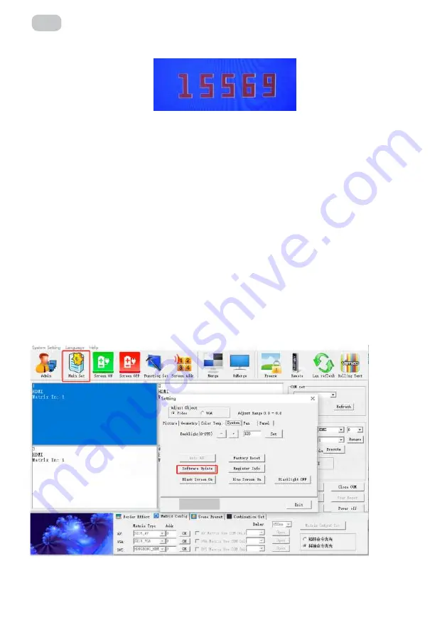
3.10.6 software upgrading
1.
Copy the software MERGE.bin to the root directory of the USB stick without changing
the file name.
2.
Insert the USB disk into the USB port of the video wall.
3.
As in Figure 21, click on the software upgrade, the screen will become blue, the progress
of software update will be displayed in the upper right corner, and the power indicator
will flash green/orange alternately, and the upgrade will restart automatically after
completion.
Note:
This function in the upgrade process, please do not power off and unplug the USB
disk, otherwise it will damage the machine
Summary of Contents for VE55L-A
Page 1: ...DISPLAY User Manual V2 0 VE55L A FOR VE55L A...
Page 9: ...9 EN 55 inch 3 5mm Bezel Model...
Page 30: ...30 UA 1 2 3 4 5 6 7 8 9 10 11...
Page 31: ...31 UA 12 13 14 15 16...
Page 33: ...33 UA 1 4 The structure of the system 2 2...
Page 34: ...34 UA 1 5 1 2 3 1 2 3 4 1 2 VGA DVI 1 2 VGA DVI 3 4 5 DVI DDC...
Page 36: ...36 UA 2 2 55 3 5...
Page 38: ...38 UA 1 3 3 1 2 2 Refresh COM Open 1 2...
Page 40: ...40 UA 4 3 6 2 2 4 Execute Image Freezing...
Page 41: ...41 UA 5 6 Eliminate the border...
Page 43: ...43 UA Fig 10 3 8 1 Matrix Enable 9 10 2...
Page 44: ...44 UA 3 9 16 Save Scene Load Scene 11...
Page 45: ...45 UA 3 10 1 Admin 111111 12 13 2 Main Set...
Page 50: ...50 UA 3 10 8 22 22 3 11 1 Admin 111111...
Page 51: ...51 UA 23 24 2 Function Set Serial port Network port Control mode Server settings IP Adress...
Page 52: ...52 UA 3 12 System Settings Title Set 25 26 Title User name Company URL URL User LOGO...
Page 53: ...53 UA 4 RJ45 to interface line sequence 27 28 Open URL 3 13 4 RJ45 TX RX GND 2 3 5...
Page 54: ...54 UA 5 5 1 Commented VG72 Commen 5 2 1 RJ45 IN 5 3 1 MENU 29 30 Input HDMI2 HDMI2 MENU...
Page 56: ...56 UA 9 25 1 18 04073 36 5...
Page 57: ...57 RU 1 2 3 4 5 6 7 8 9 10 11...
Page 58: ...58 RU 12 13 14 15 16...
Page 60: ...60 RU 1 4 The structure of the system 2 2...
Page 61: ...61 RU 1 5 1 2 3 1 2 3 4 1 2 VGA DVI 1 2 VGA DVI 3 4 5 DVI DDC...
Page 63: ...63 RU 2 2 55 3 5...
Page 65: ...65 RU 1 3 3 1 2 2 COM Refresh Open 1 2...
Page 67: ...67 RU 4 3 6 2 2 4 Execute Image Freezing...
Page 68: ...68 RU 5 6 Eliminate the border...
Page 70: ...70 RU Fig 10 3 8 1 Matrix Enable 9 10 2...
Page 71: ...71 RU 3 9 16 Save Scene Load Scene 11...
Page 72: ...72 RU 3 10 1 Admin 111111 12 13 2 Main Set...
Page 77: ...77 RU 3 10 8 22 22 3 11 1 Admin 111111...
Page 78: ...78 RU 23 24 2 Function Set Serial port Network port Control mode Server settings IP Adress...
Page 79: ...79 RU 3 12 System Settings Title Set 25 26 Title User name Company URL URL...
Page 80: ...80 RU 4 RJ45 to interface line sequence 27 28 User LOGO Open URL 3 13 4 RJ45 TX RX GND 2 3 5...
Page 81: ...81 RU 5 5 1 Commented VG72 Commen 5 2 1 RJ45 IN 5 3 1 MENU 29 30 Input HDMI2 HDMI2 MENU...
Page 83: ...83 RU 9 25 1 18 04073 36 5...
Page 86: ...86 RU 2E 1 2 60 3 4 5 6 7 36 _____________________________________________________________...
Page 88: ......


