247Security Inc. | 4400 North Point Parkway, Suite # 158, Alpharetta, GA 30022, USA | 1-866-693-7492 | www.247securityinc.com
OSD stands for On-Screen-Display, this feature embeds Sensor name (End-users can
assign a name for each individual sensor in the sensor configuration tab that we will address
later) into video files. When playing back the video, the sensor(s) can be identified by the
embedded text on the video. Placing a check mark on the OSD box activates this feature.
Again, we can define the Pre-Recording (in seconds) and Post-Recording (in seconds)
in the sensor trigger recording process. It is a similar process that we discussed above in Event
Marker Menu. Maximum of 5 minutes (300 seconds) can be entered into these fields.
5.2.2.6
ALARM CONFIGURATION MOTION SENSITIVITY
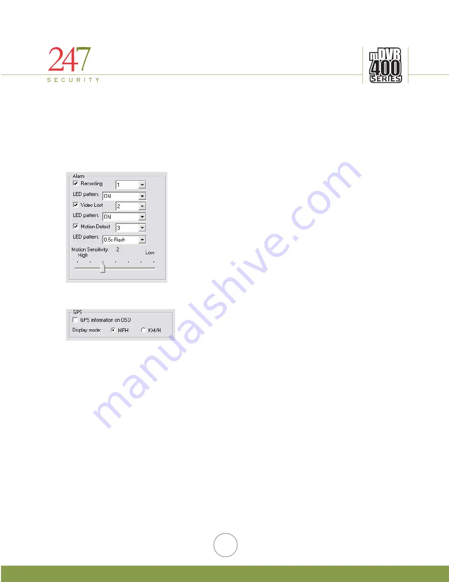
In the DVR400, there are four digital outputs that can
be used to configure as Alarms. The Alarm menu on the left
demonstrates an example of how to use the alarm feature. You
can assign any of these events to a specific output by changing
the output number. For instance, recording status is sent to
Digital Output 1, Video Lost status is sent to Digital Output 2
etc…
You can also control how the alarm indicator LED
works, either flashing by interval or permanently ON when the
event occurs. Placing a checked mark on any of these alarm
events will activate the alarm feature. Motion sensitivity is
adjustable by moving the bar to a desired level.
5.2.2.7
ENABLE GPS
or KPH.
GPS information feature is also available on
DVR400 Series. GPS feature allows End-User to record
data from GPS satellite such as speed, locations etc…
Speed is displayed in MPH
Additionally, we can use GPS data to compose a map, or route trip of vehicle. Place a
checked mark in that box to activate the GPS feature. The DVR400 displays GPS information
on the screen as well as keeping a record of GPS data on storage media.
20


