


TN9 Infrared Thermometer Module
http://www.ZyTemp.com
REV. 07/20/2004
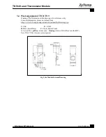
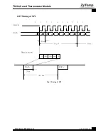
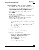
4 Serial Output
4.1 Typical Diagram
V
+3V
TTL
TN9 D
Interface PC
C
(MCU)
G
A
Clock +Data+GND RS-232 or other
Fig 6. Typical Diagram
TN9 to TTL Interface (MCU)
V:Vcc
D:Data
C:Clock (2KHz)
G:GND
A:ActionKey (When Pull Low, the device will measure Tbb continuousely.)
Note: Data Pin is High when there is no data out, Time Out > 2ms


