Zub machine control MK1/100 Скачать руководство пользователя страница 5

End Switch 

zub machine control AG 

Manual MK1/100

 · 

Hardware Installation


Seite 5 

MK1/100 

You can now carry out a test of the end switch. After activation of the end switch, an error 
must occur and the red Error LED must be lit. 

In order to enquire about the error, open the error enquiry window as described above. The 
error message "End switch reached" must appear. Delete the error message with 

ESC

 and 

J


(for Yes). 


Switch off the power supply, before you connect the encoder to the 

MK1/100

For error-free operation it is necessary for the encoder to be connected with the

 MK1/100

 via 

a shielded cable. In making the connection it is important to keep the cables as short as 
possible and to route them as far away from power cables as possible. Encoders with TTL or 
open collector outputs can be used, which have a supply voltage of 5 V. 


The precise allocation of the encoder jack and the significance of the signals (temporal trends 
and interrelationships) can also be found in the hardware reference section. 

The encoder is mounted on the motor shaft. In order to test the encoder, it is necessary that 
the motor shaft is able to move freely. 

The motor must not be connected during this test. 

In order to test the encoder in a simple way at first, carry out an APOS test program. Select 
the APOS menu item 

File 

 Load.


With the keys

 Pos1

 and 

End,

 select the document "DREHGTST.M“. You can also enter the 

name of the document directly. The entry must be completed with the 

Enter

 key. 

After the APOS program has been loaded, it must be started as follows: 

Leave the Editor window with the 

ESC 

key. Then select the menu 

Execute


 Start program 

with the

 cursor

 keys and the 

Enter 

key. When the 

Enter

 key is pressed, the program is 

processed. 

In the output window, you will now see a new position value displayed every half a second. 
After a full revolution of the motor shaft by hand, the position value should amount to four 
times the encoder count per turn. For instance, if the encoder count per turn is 500, you 
should receive a position value of 

±

2000. After a further revolution in the opposite direction, 

the position value should be zero. 
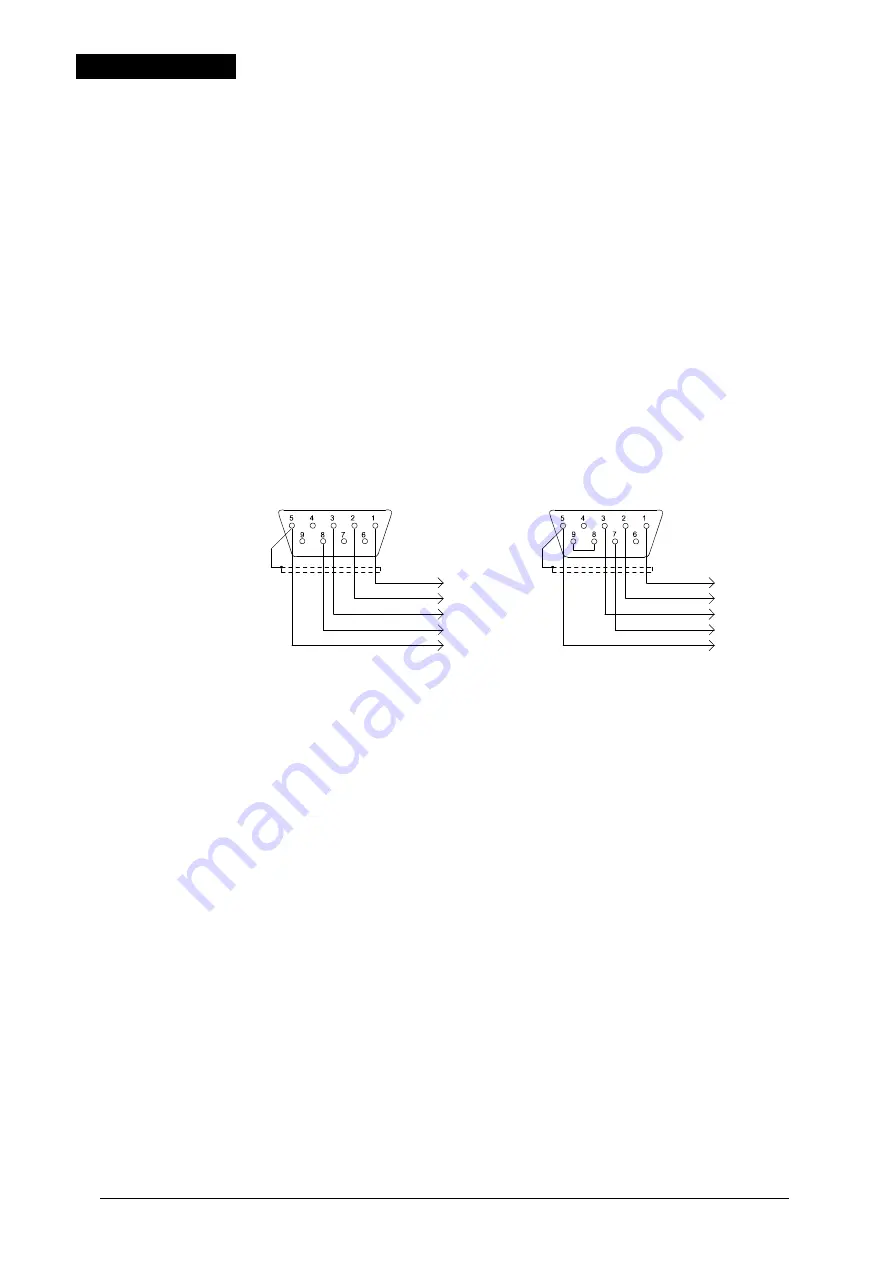
 

End Switch 

Incremental Encoder 

! ! !  

! ! !  

Encoder with  

negative

 index impulse


Encoder 

Encoder with  

positive

 index impulse


Encoder 


+ 5 V 
track A 
track B 
/Index 
GND


screen


+ 5 V 
track A 
track B 
/Index 
GND


screen


                 Z&B Werkbild: mk1drehb 

to the encoder 

to the encoder 

bridge


Содержание MK1/100

Страница 1: ...zub machine control AG 2013 machine control AG MK1 100 Mono axis compact control Manual for installation and hardware reference...

Страница 2: ...stleistung de This manual is set in ITC MixageBQ To improve utilization of the printed manual and the on line help with a variety of programs only special characters from the Symbol and Wingdings font...

Страница 3: ...se of the Encoder and Reference Switch 7 Program testing 7 First steps towards programming 7 Setting the Control Parameters 8 Troubleshooting 9 Hardware Reference 10 Power Supply 10 CPU 10 COM Interfa...

Страница 4: ...case no error is present In order to carry out the communication test with the computer select the menu Execute Error State in the APOS program with the cursor keys and and the Enter key A window ope...

Страница 5: ...essary that the motor shaft is able to move freely The motor must not be connected during this test In order to test the encoder in a simple way at first carry out an APOS test program Select the APOS...

Страница 6: ...be fixed in place and existing brakes are to be released Test the motor with the APOS program MOTORTST M Inform you about File Load and Execute in the section Incremental Encoder After the program has...

Страница 7: ...in the execution window read about the possible causes of the error and the corresponding steps to be taken at the end of this section In order to facilitate initial installation the delivery paramete...

Страница 8: ...e PID filter used is described by the following formula u n KP e n KI e n KD e n e n 1 u n Correction factor in n e n Control error in n n Sample cadence n Sample cadence for differential factor KP Pr...

Страница 9: ...rect interface on the PC with the APOS program Use the original cable or check the cable assignment The encoder does not function Wrong cable assignment Encoder needs higher supply voltage than 5V Che...

Страница 10: ...commands Application program memory 128 kB EEPROM Signal transfer to RS232 standard Baud rate 9600 bit s Data format 8 bit Stop bit 1 Parity none Signals RxD TxD GND Hardware handshake signal none Sof...

Страница 11: ...10800 rpm Input voltage low UEL 0 0 8 V Input voltage highUEH 2 6 V 6 V Input currentIELow 0 mA Input currentIEHigh 2 5 mA 9 mA Pull up Widerstand Rup 1 k internal Number 1 Logic central stop low act...

Страница 12: ...ircuit proof Logic positive connecting to GND APOS program sample OUT 1 1 means output 1 after GND switched by UB Maximum load current IAN 100 mA Voltage drop 1 8 V for IAN Switching frequency maximum...

Страница 13: ...Operating temperature 0 C 50 C Storage temperature 20 C 70 C Relative humidity 75 without dew Design housing with brackets for easy assembly enclosers for 19 systems option Width 105 mm with brackets...

Страница 14: ...ps towards programming 8 H Hardware Reference 10 I Impressum 2 Incremental Encoder 5 Index Impulse of the Encoder 7 Index Impulse of the Reference Switch 7 Initial operation 4 Inputs Control inputs 12...

Отзывы: