


User Manual
This document is not allowed to
transmit without ZTE Corporation
’s
permission
©ZTE CORPORATION All rights reserved
21
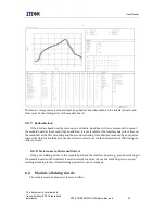
See the module’s power-on/off time sequence in figure 4-3 below:
Figure 4-3 Power-on/off time sequence
VDDIO
The module has one LDO voltage output pin, which can be used to supply external power to the
main board. The voltage output is available only when the module is on. The normal output voltage
is 2.8V, and users should absorb the current from this pin as little as possible (less than 10mA).
Generally, it is recommended to use this pin to pull up the chipset PIN as per the requirements of
level matching. Therefore, it’s not recommended to use this pin for other purposes.
Other advice
In order to make sure the data is saved safely and guarantee the safety of module’s data, please
don’t cut off the power when the module is on.
4.2
UART interf ace
MG2639_V3 module provides an integrated full duplex UART1 interface (shortly referred to as
UART interface) and an accessorial UART2 interface. The default baud rate is 115200bps and the
external interface adopts 2.8V CMOS level signal, which conforms to RS-232 interface protocol. The
UART1 interface could be used as serial interface for AT commands, data service. The UART2
interface can be used to debug the applications.


